00195655-04_SM_X-Series_FSE_en.pdf - 第70页
Service Work Gantries 3.3.11 Fitting and Removing the Y Axis Bumper 70 Ser vice Manual (internal ver sion) SIPLACE HF and X Series 3.3.11 3 . 3 . 1 1 F it t in g a n d R e m o v in g t h e Y A x is B u m p e r Fitting an…
Service Work
3.3.10 Replacing the Y Linear Motor - Primary Part Gantries
Service Manual (internal version) SIPLACE HF and X Series 69
3.3.10
3.3.10 Replacing the Y Linear Motor - Primary Part
Replacing the Y Linear Motor - Primary Part
Item number
▪ Linear motor Y drive, complete (D3, X-Series) [03013459-xx]
Removal
Installation
Settings
► Check the axis dynamics of the drives removed.
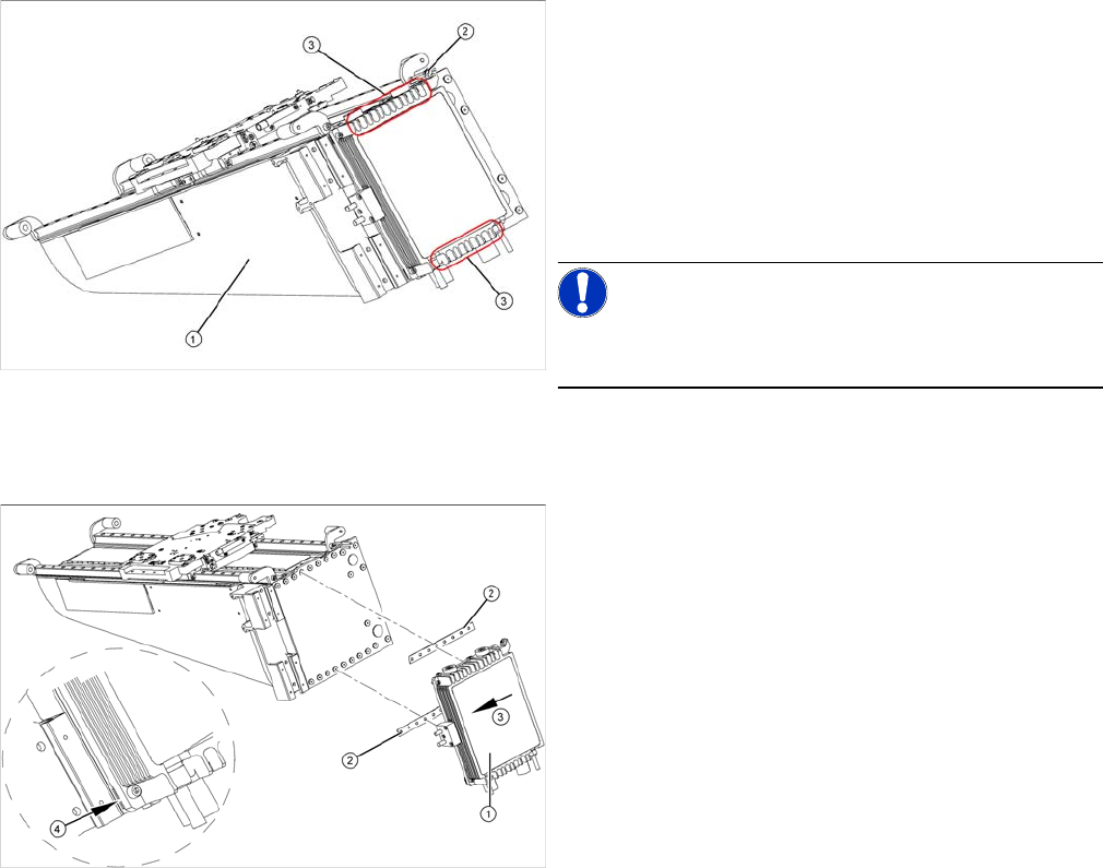
► Dismantle the gantry (see "3.3.3 Replacing Gantries"
[ ➙ 47]) and put it in a suitable place (1).
► Remove the cable ties holding the connection cable.
► Remove the proximity switch mount (2) and proximity
switches.
► Undo the 16 fastening screws (3). Make sure you do
not lose the insulating plates underneath the screws.
These need to be used again later on.
NOTICE!
The fastening screws have been secured with locking
varnish (Loctite 241).
► Loosely fasten the new Y drive (1) with the screws
and insulating plates (2) provided. Use Loctite 241 to
secure them.
► Press the motor upwards, within the tolerance of the
drilling (3). If you do not do this, the motor could lie on
the bottom guides. Now tighten the two center
screws.
► Make sure that the ends of the insulation plates (4)
are not protruding (these plates are not symmetrically
centered). If necessary, press these back in with a
suitable tool (e.g. screwdriver).
► Then tighten all 16 fastening screws with the aid of a
torque wrench (first in the center, then at the top and
lastly at the bottom) (5.5 N).
► Install the proximity switch mount and proximity
switches.
► Fasten the connection cable so that it will not be in the
way when installing the gantry.
► Install the gantry and the trailing cable.
Service Work
Gantries 3.3.11 Fitting and Removing the Y Axis Bumper
70 Service Manual (internal version) SIPLACE HF and X Series
3.3.11
3.3.11 Fitting and Removing the Y Axis Bumper
Fitting and Removing the Y Axis Bumper
Parts and equipment
Removal for X-Series and D3
► Remove the relevant changeover table from the machine.
► Loosen the coated fastening screws on the Y stopper and remove them.
CAUTION
Procedure
The four fastening screws on the Y stopper need to be tightened with the corresponding angle
disc, using a special procedure (angle-controlled tightening method). This procedure is re
-
quired to ensure that the tightening torque is achieved with the necessary precision.
Once the screws have been tightened for the first time, these may not be loosened again, as
the angle-controlled method brings the screws to their stress yield point.
If the screws are loosened and retightened, there is no guarantee that the tightness will be suf
-
ficient. In a worst case scenario, the screws may break when retightened.
If you need to loosen the screws, use new screws afterwards.
► Do not tighten using the torque key!
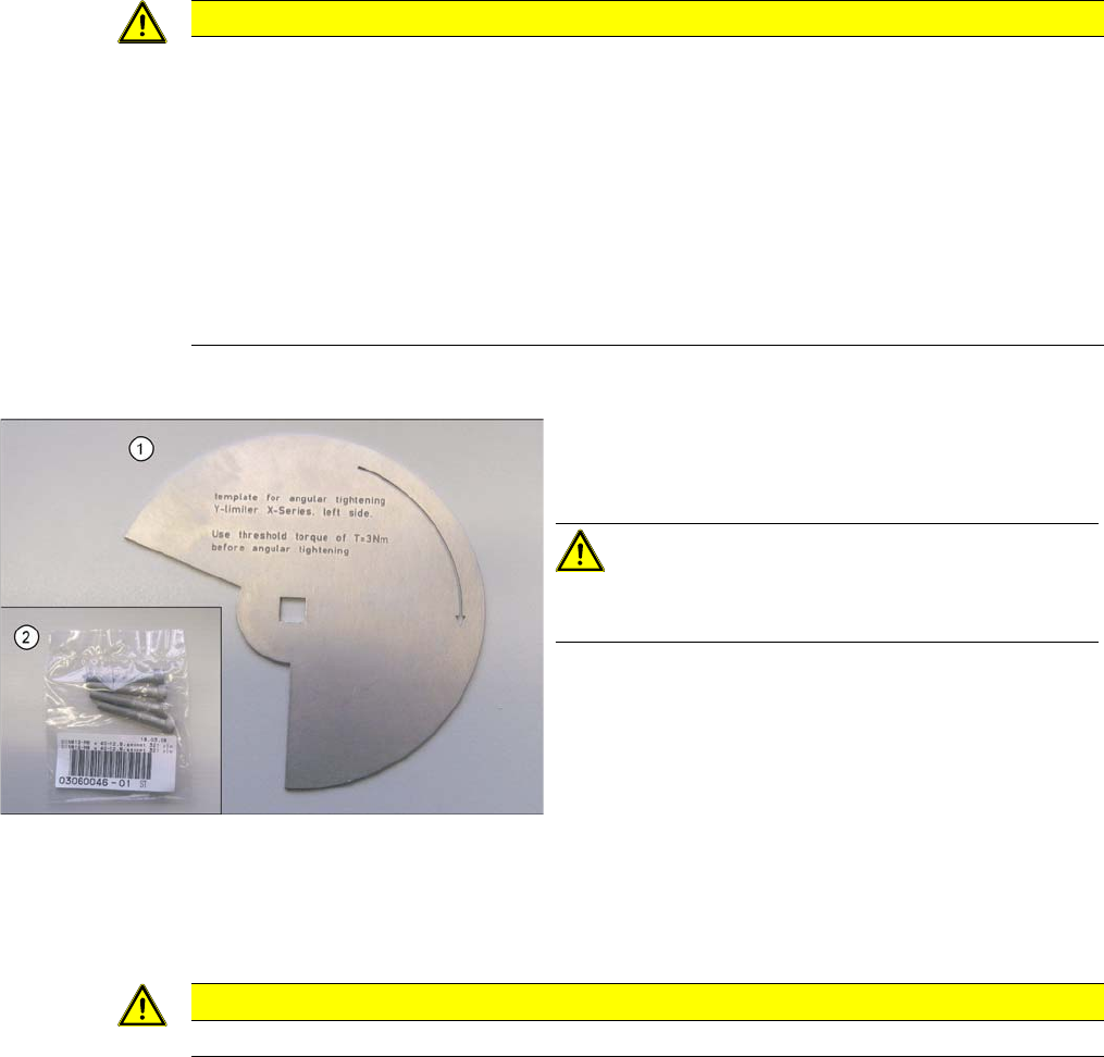
▪ Angle disc [03065367-xx] (1)
▪ 4 fastening screws (DIN912-M6 x 40-12.9, geomet
321 plus VL) [03060046
-
xx] (2)
CAUTION!
When replacing or dismantling the Y axis bumpers, al
-
ways use new screws!
▪ Red screw locking varnish
▪ Standard tools
CAUTION
Take care not to lose the washers and friction springs.
Service Work
3.3.11 Fitting and Removing the Y Axis Bumper Gantries
Service Manual (internal version) SIPLACE HF and X Series 71
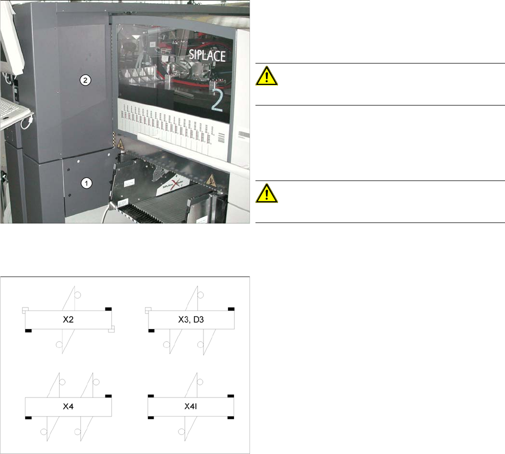
Removal for X4I
Installation
► Remove the relevant changeover table from the ma
-
chine.
► Undo and remove the two screws fastening the bot
-
tom cover (1).
CAUTION!
Take care not to lose the screws etc..
► Undo and remove the two screws fastening the upper
cover (2).
► Loosen the coated fastening screws on the Y stopper
and remove them.
CAUTION!
Take care not to lose the washers and friction foils.
All the Y stoppers marked black in the diagram need to
be fitted with the help of the angle disc.