00195655-04_SM_X-Series_FSE_en.pdf - 第45页
Service Work 3.3.2 Replacing the Guide Trolley [00386872-xx] Gantries Service Manual (internal ver sion) SIPLACE HF and X Series 45 3.3.2 3 . 3 . 2 R e p la c in g t h e G u id e T r o lle y [ 0 0 3 8 6 8 7 2 - x x ] Rep…
Service Work
Gantries 3.3.1 Replacing the Trailing Cable
44 Service Manual (internal version) SIPLACE HF and X Series
► Fix the two clamps (8) and (9) and the trailing cable console (7). Use Loctite 241 to secure them.
► Tighten the fastening screws for the trailing cable console (7) crosswise.
See also
3.3.1.4 Handling the Hose Unlocking Tool [03047090-xx] [ ➙ 24]
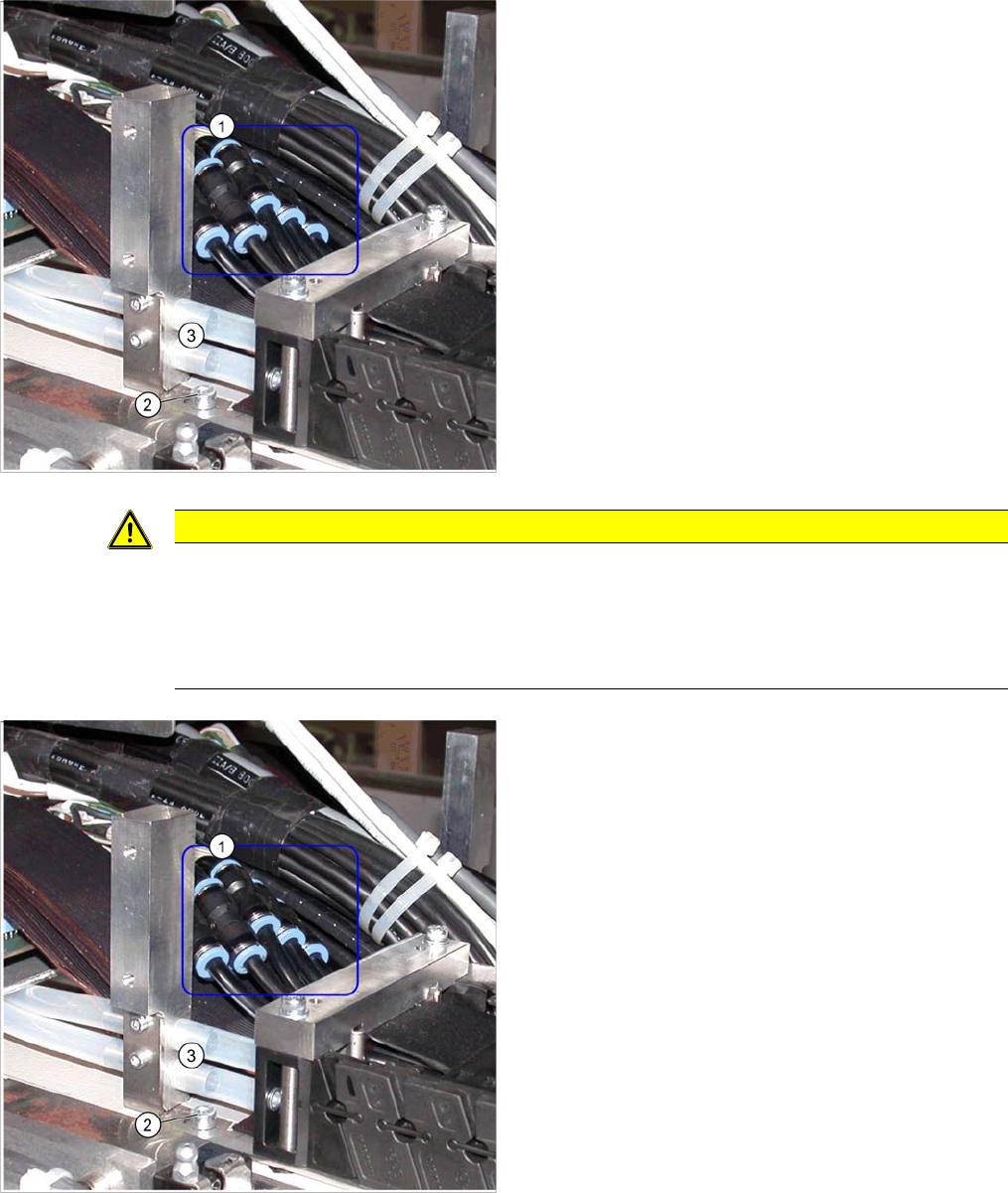
► Fit the trailing cable mount (2) onto the machine
base.
Connect the pneumatic hoses to the pneumatic distribu
-
tor in the machine base.
The pneumatic hoses are run to the pneumatic distributor
in the machine base. The existing pneumatic hoses,
which are run in the machine, need to be severed and
connected to the trailing cable (1) at the exact position,
with the help of hose couplings [03049770
-
01].
► Place the gauge at the stopper edge of the mount and
label the pneumatic hoses for the trailing cable. See
also "3.3.1.7.2 Preparing the Trailing Cable" [ ➙ 37].
CAUTION
Shortening and connecting the pneumatic hoses
► Label the order of pneumatic hoses (from 1 to 7 – inside to outside). This is important to
ensure that the hoses are then correctly connected again after cutting.
► Make sure that you use the correct gauge for your gantries and that you do not cut the pneu
-
matic hoses too short.
► Cut the pneumatic hoses of the new trailing cable at
the marked points.
► The seven hoses of the new trailing cable are con
-
nected to one another. Carefully separate these from
one another, up to the mount.
► Connect the pneumatic hoses for the trailing cable
with the hose couplings (1). Observe the labeling (1-
7 from inside to outside).
► Reconnect the Y motor cooling tubes to the connec
-
tion pieces.
► If you have the "Vacuum pump" option, reconnect the
pneumatic hoses.
► Fasten new cable ties at the original points.
► Replace all dismantled cover plates in their original
positions.
Service Work
3.3.2 Replacing the Guide Trolley [00386872-xx] Gantries
Service Manual (internal version) SIPLACE HF and X Series 45
3.3.2
3.3.2 Replacing the Guide Trolley [00386872-xx]
Replacing the Guide Trolley [00386872-xx]
The linear guide rails of the X and Y axes use the same 4 guide trolleys.
The X motor or head mount is fitted to the guide trolleys of the linear guide rails in the X direction, while
the X gantry is fastened to the guide trolleys in the Y direction.
The spare parts kit [00386872-xx] contains important parts which are needed when replacing the X axis.
▪ 2 x guide trolley Bosch-Rexroth size 15 LLD [03020300-xx]
▪ 2 x insertion tool for guide trolley BR size 15 LLD
▪ 2 x guide trolley Bosch-Rexroth size 15 lg LLD [03020301-xx]
▪ 2 x insertion tool for guide trolley BR size 15 lg LLD
▪ 4 x dismantling screw [03041576-xx]
▪ 8 x DIN912-M4 x 60-8.8 [00845036-xx
▪ 1 x plastic gauge 0.4x100x500 mm [0377435-xx]
▪ 1 x plastic pad 500x50x20 mm [0377436-xx]
3.3.2.1
3.3.2.1 Requirements for Replacement at X Gantry
Requirements for Replacement at X Gantry
3.3.2.2
3.3.2.2 Requirements for Replacement at Y Gantry
Requirements for Replacement at Y Gantry
In order to replace the guide trolley in the Y direction, you must first dismantle the X gantry.
CAUTION
Never replace guide trolleys individually!
Always replace all 4 guide trolleys belonging to an axis at the same time.
CAUTION
Send old guide trolleys back!
For quality analysis purposes, send all old guide trolleys with inserted insertion tool back to
SIPLACE. Record a siebel defect for this procedure.
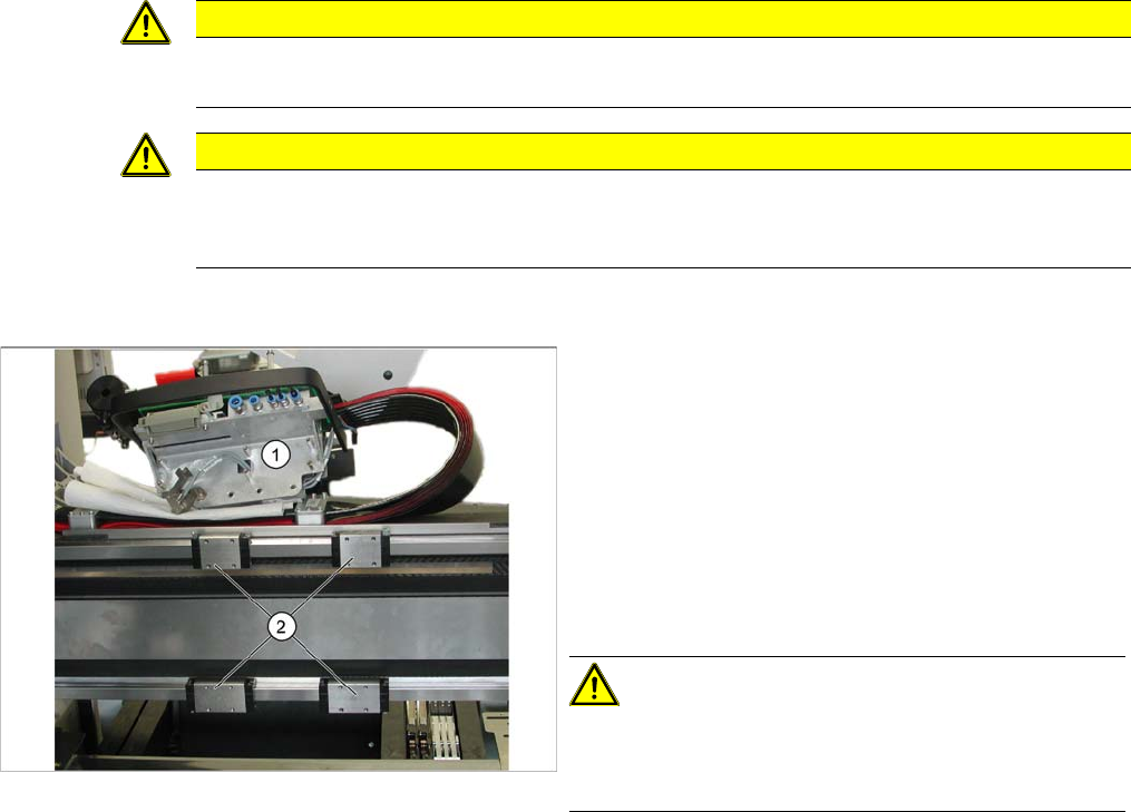
In order to replace the guide trolley (1) in the X direction,
you must perform the following preparatory steps:
► Dismantle the placement head.
► Dismantle the limit switch – if present (no long neces
-
sary from A364).
► Dismantle the PCB camera.
► Dismantle the X incremental encoder.
► Remove the X motor or head mount (2) and carefully
place this down on the gantry.
CAUTION!
Avoid damage to the vacuum hoses!
Do not place the head mount directly on the vacuum hos
-
es but on a suitable, soft surface.
► The adjacent diagram shows the initial situation.
Service Work
Gantries 3.3.2 Replacing the Guide Trolley [00386872-xx]
46 Service Manual (internal version) SIPLACE HF and X Series
3.3.2.3
3.3.2.3 Removing the Guide Trolley
Removing the Guide Trolley
3.3.2.4
3.3.2.4 Fitting the Guide Trolley
Fitting the Guide Trolley
► Now fit the X motor or the head mount with all the relevant connection leads.
► Fit the limit switch – if present (no longer necessary from A364).
► Dismantle the X incremental encoder.
► Install the PCB camera.
► Fit the placement head.
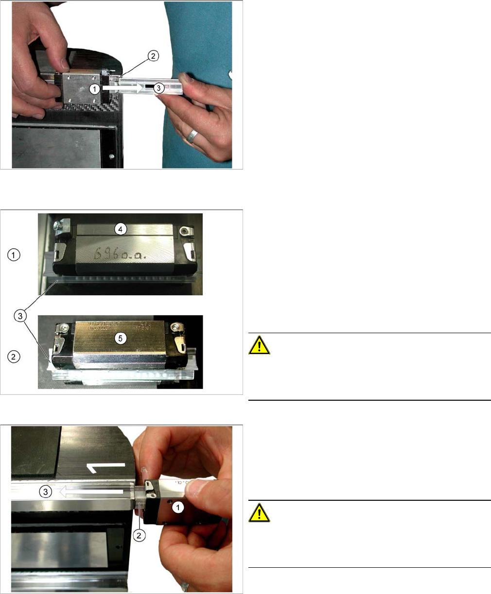
The spare parts kit includes 4 insertion tools, which
should be used to help you remove the guide trolley.
These should ensure that the guide trolley is sent back for
quality analysis in its "installation state".
Removal is identical for all guide trolleys (1).
► Dismantle the two stoppers on the X guide rails.
► Position the insertion tool (3) exactly on the linear
guide rails (2).
► Push the guide trolley onto the insertion tool (3).
All guide trolleys have an upper side (1) and an underside
(2).
▪ The upper side (1) has a smoothed stopper edge (4).
Ensure that this side always points upwards in all in
-
stallation positions.
▪ The underside (2) has just been mill cut (5) and has
no stopper edge.
▪ All guide trolleys are supplied with an insertion tool
(3).
CAUTION!
Do not pull out the insertion tool!
Never pull out the insertion tool before fitting the guide
trolley.
Installation is identical for all guide trolleys (1).
► Position the insertion tool (3) exactly on the linear
guide rails (2).
► Push the guide trolley off the insertion tool (3) and
onto the linear guide rail.
CAUTION!
Do not damage it!
Make sure that the guide trolley is not damaged when you
push it.