00195655-04_SM_X-Series_FSE_en.pdf - 第110页
Service Work Cutter 3.9.1 Replacing the Cutter Blades [03009259- xx] 110 Service Manual (internal ver sion) SIPLACE HF and X Series ► Reinsert the tape deflector unit (3) and screw in the 4 hexa gon socket-head screws (4…
Service Work
3.9.1 Replacing the Cutter Blades [03009259-xx] Cutter
Service Manual (internal version) SIPLACE HF and X Series 109
Preparation
Installation
► Use an SW 10 open-ended wrench to push against the relevant joint (3) and then tighten both screws
(2) to a torque of 2.7 – 3.0 N.
► Replace the two covers (caps).
► Place the 2 new spacers (4) to the left and right of the moveable blade. The spacer side marked with
a number must face away from the blade.
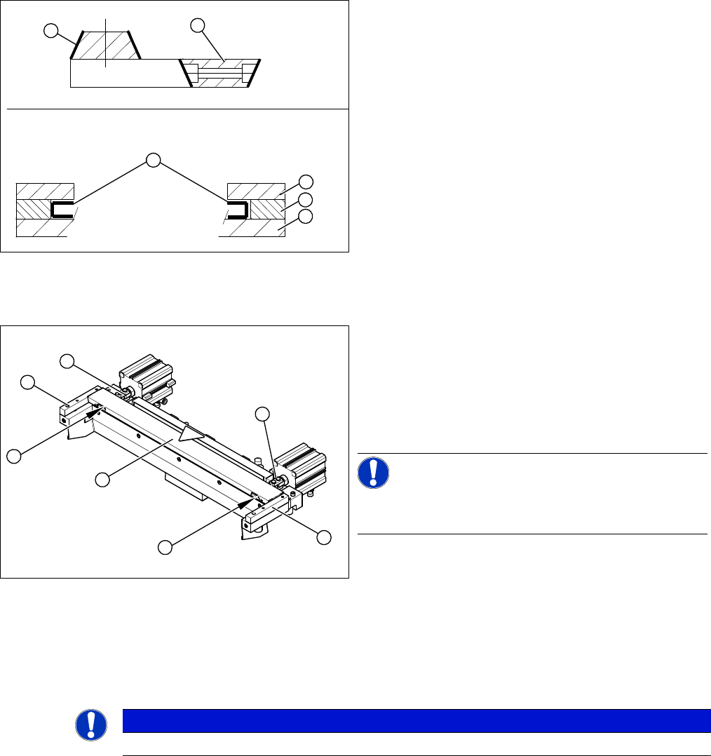
1. Stationary blade
2. Moveable blade
3. Sliding surfaces to be lubricated
4. Holding-down device
5. Spacer
6. Contact surface
► Make sure the cutter is in the correct rotary position
(see the slant of the blade).
► Check the positioning of the individual blades to one
another.
► Before installation, lubricate the sliding surface of the
moveable blade.
1
6
5
4
3
2
► Correctly insert the moveable blade (1) into the cutter
and shift it along to its original installation position.
► Apply Loctite no. 243 to the two M4 screws, to fasten
the joint in the moveable blade.
► Insert the screws (2) into the left and right holes, pro
-
vided in the moveable blade.
NOTICE!
Make sure that the joint (3) can slide into the slot (= anti-
twist function) in the moveable blade without obstruction.
2
3
4
1
4
3
2
NOTICE
The spacers and blades are matched!
Service Work
Cutter 3.9.1 Replacing the Cutter Blades [03009259-xx]
110 Service Manual (internal version) SIPLACE HF and X Series
► Reinsert the tape deflector unit (3) and screw in the 4 hexagon socket-head screws (4) by hand.
► Push the spacers (with inserted shim) as far as possible in the direction of the moveable blade. The
maximum permissible gap is 1.0 mm.
► In this position, tighten the 4 screws (4) on the tape deflector holder crosswise (tightening torque).
► Remove the two feeler gauges.
► Insert the new stationary blade (5) in the correct position and screw tight.
Final work
If the gap is correct:
► Replace the protective plate, baffle plate and cover plate. Make sure that the edges are parallel.
► Remove the clamps form the cutter/ remove the cutter from the assembly plate.
► Fit the cutter.
► Lubricate the contact/slide surfaces for the moveable
blade, as described in the section "Preparation".
CAUTION!
Do not lubricate the blades themselves.
► Place a feeler gauge (0.5 - 1.0 mm thickness) on the
left and right, between the spacer and the front of the
moveable blade (1).
► Place the previously removed holding-down device
(2) onto the new spacers.
⇨ The holding-down devices with function status 03
are designed for use with cutters of function status
-04 (= with tape deflector).
1
2
4
1
5
4
3
2
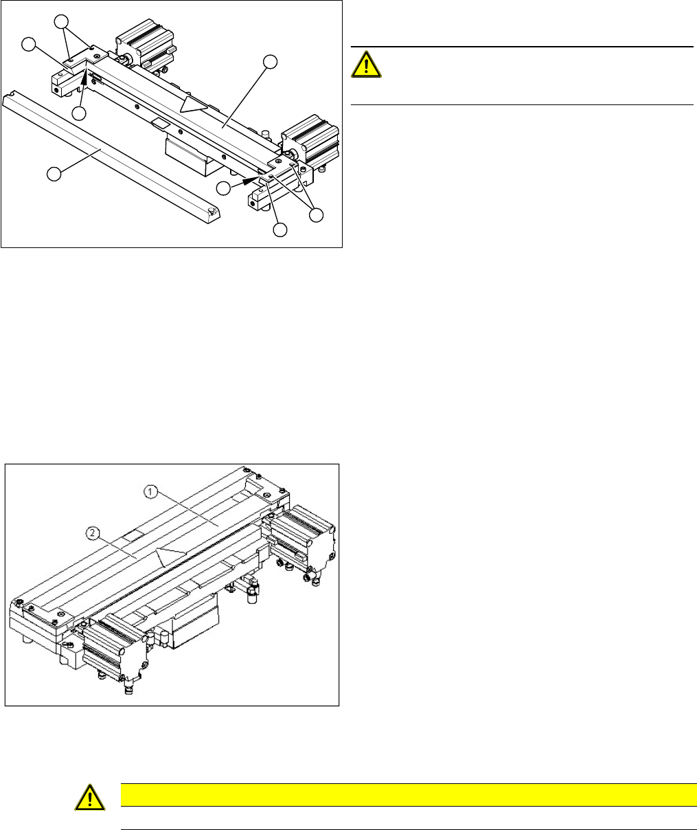
► Use a feeler gauge to check the gap between the
tape deflector (1) and the moveable blade (2), along
the entire length and width of the blade.
⇨ The 0.05 mm feeler gauge should fit through the
gap.
⇨ The 0.25 mm feeler gauge should not fit through
the gap.
If the gap is not correct, check:
▪ Whether the wrong holding-down device has been in
-
stalled (with function status < 03)
▪ The holding-down devices are those designed for
cutters with function status -04 (= with tape deflector)!
▪ Whether the blades, tape deflector etc. were cleaned
before installation
CAUTION
Make sure that the cables and hoses are not trapped or subjected to excess strain.
acpage