00195655-04_SM_X-Series_FSE_en.pdf - 第84页
Service Work C&P20 Placement Head 3.5.1 Replacing the E/D Transformer (Collec tor Ring) - FSE 84 Ser vice Manual (internal ver sion) SIPLACE HF and X Series 3.5 3 . 5 C & P 2 0 P la c e m e n t H e a d C&P20 …
Service Work
3.4.7 Width Adjustment Unit Modular PCB Conveyor System
Service Manual (internal version) SIPLACE HF and X Series 83
3.4.7.2
3.4.7.2 Setting the Pneumatic Cylinder Proximity Switch on the Adjustment Unit
Setting the Pneumatic Cylinder Proximity Switch on the Adjustment Unit
► Start SITEST
► Set any conveyor width. The adjustment units are positioned directly under the conveyor side.
► Start the I/O menu.
► Activate the pneumatic cylinder.
► Set the proximity switch on the pneumatic cylinder so that the LED (H35/H36/H37 for TSP 301) (H64/
65 for TSP 201) shines when connected.
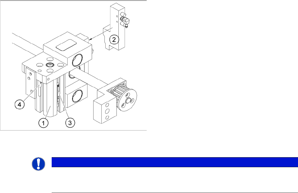
Overview of the proximity switches on the adjustment unit
for width adjustment
1. Short-stroke cylinder
2. Solenoid valve
3. Proximity switch for pneumatic cylinder (for "locking
pin up" recognition)
4. Proximity switch for adjustment unit(for conveyor side
recognition)
The proximity switch (3) on the adjustment unit cylinder
should operate when the adjustment unit pin is pushed
out by the pneumatic cylinder and therefore connected to
the conveyor rail. This signal enables the width adjust
-
ment motor.
NOTICE
Setting
The proximity switch on the pneumatic cylinder is set in its engaged state.
The proximity switch is off when the cylinder is extended into free space.
Service Work
C&P20 Placement Head 3.5.1 Replacing the E/D Transformer (Collector Ring) - FSE
84 Service Manual (internal version) SIPLACE HF and X Series
3.5
3.5 C&P20 Placement Head
C&P20 Placement Head
3.5.1
3.5.1 Replacing the E/D Transformer (Collector Ring) - FSE
Replacing the E/D Transformer (Collector Ring) - FSE
Preparation
NOTICE
The star is not a spare part!
The star is not a spare part and is only removed if the E/D transformer needs to be replaced.
CAUTION
Different E/D transformer used for CP20 / CP20A!
The E/D transformer is used for the C&P20 [03007711-xx].
Only the E/D transformer may be used on the C&P20A of the X4I [03058629-xx]!
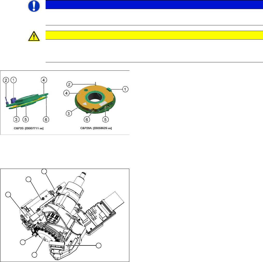
Old and new ED transformers
▪ The new E/D transformer [03058629-xx] consists of a
stationary and a rotating part.
Three sliding contacts (5) transmit the direct current
voltage (24V/4A).
▪ The CAN bus signals are transmitted contactless.
▪ Connector (1) to intermediate distributor
▪ A centering pin (2) fixes the stationary part (4) in
place.
▪ The rotating part (3) is fixed to the star carrier with five
screws, which can be loosened via the service open
-
ing (6).
1. Component camera
2. Silencer
3. BE-sensor
4. Z axis
5. Pressure control valve
6. Return unit
► Remove the component camera (1).
► Remove the silencer (2).
► Remove the pressure control valve (5).
► Remove the Z axis (4) with return unit (6).
► Remove the component sensor (3).
6
1
5
4
3
2
Service Work
3.5.1 Replacing the E/D Transformer (Collector Ring) - FSE C&P20 Placement Head
Service Manual (internal version) SIPLACE HF and X Series 85
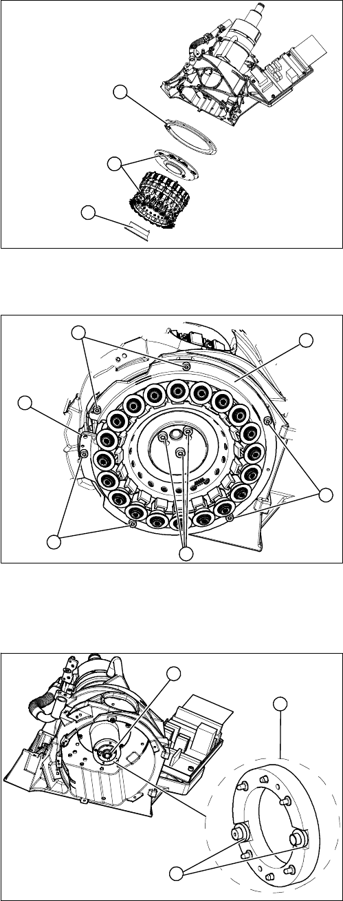
Removing the star
1. Hold circuit - vacuum unit
2. Star, complete with E/D transformer
3. Raceway
► Remove the hold circuit vacuum unit (1).
► You can now access the star (2).
1
3
2
► Loosen the 6 fastening screws (2) holding the race
-
way (1).
► The raceway is fixed to the Z axis position with pins
(3). Gently lever the raceway off with a suitable
screwdriver.
⇨ The raceway can not be removed and will remain
hanging from the star. Carefully place the raceway
onto the segments.
► Loosen the 3 fastening screws (4) holding the star
and carefully lift these out of the star carrier.
⇨ Note the different lengths of the 3 fastening screws
(4). Mark their installation positions.
⇨ The connection cable is long enough to remove
the star and E/D transformer and then disconnect
outside the star carrier.
► Disconnect the E/D transformer and place the entire
unit down on a suitable surface.
► Pull the smoothed distributor disc (1) off the motor
shaft (3) of the star drive. Take care of the O ring on
the motor shaft.
► Make sure that you do not lose the 4 O rings (2) on
the smoothed distributor disc!
► Clean the 4 O rings (2) (2 on each side) on the
smoothed distributor disc and grease them slightly
with Unisilikon.
► Clean the O ring (3) on the motor shaft and grease
slightly with Unisilikon.
► Attach the smoothed distributor disc to the rotary ax
-
is.
2
2
1
4
3
2
3
1
2