00195655-04_SM_X-Series_FSE_en.pdf - 第75页
Service Work 3.4.1 Replacing the Drive Toothed Belt for the Width Adjustment System [00369662-xx] Modular PCB Conveyor System Service Manual (internal ver sion) SIPLACE HF and X Series 75 ► Feed the new drive tooth ed be…
Service Work
Modular PCB Conveyor System 3.4.1 Replacing the Drive Toothed Belt for the Width Adjustment System
74 Service Manual (internal version) SIPLACE HF and X Series
3.4
3.4 Modular PCB Conveyor System
Modular PCB Conveyor System
3.4.1
3.4.1 Replacing the Drive Toothed Belt for the Width Adjustment System [00369662-xx]
Replacing the Drive Toothed Belt for the Width Adjustment System [00369662-xx]
Tools
▪ 3 small or medium screw clamps
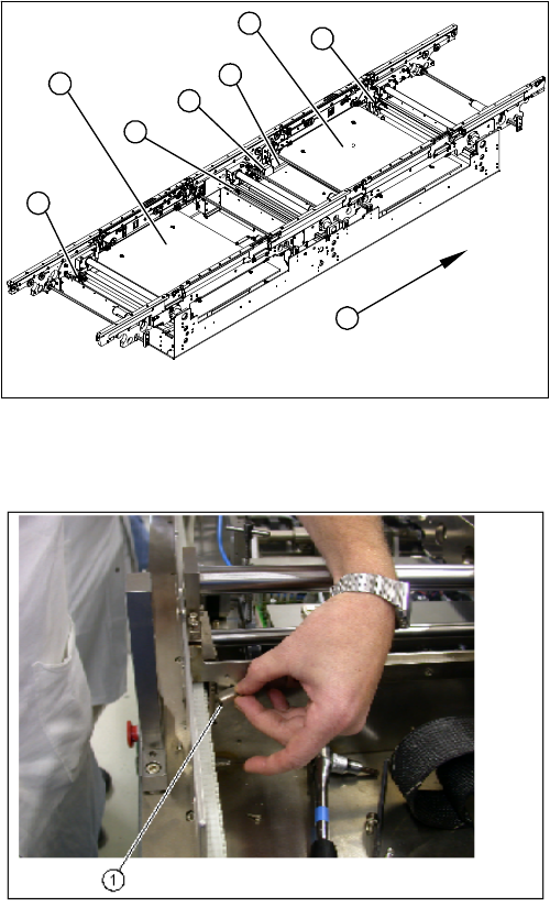
Overview
Removal/Installation
1. Adjustment unit 1,2 and 3 with recirculating spindles
2. Width adjustment stepping motor
3. Toothed belt for the drive
4. Lifting table plates PA1 and PA2
5. Transport direction
1
1
2
4
4
1
5
3
► Move the conveyor system to minimum width.
► Undo the screws fastening the lifting table plates and
remove the lifting table plates from the lifting table
unit.
► Remove the slides (1) on the deflection bearings of
the width adjustment motor.
Service Work
3.4.1 Replacing the Drive Toothed Belt for the Width Adjustment System [00369662-xx] Modular PCB Conveyor System
Service Manual (internal version) SIPLACE HF and X Series 75
► Feed the new drive toothed belt into the machine and run it over the toothed wheels.
► Fit the flange with its recirculating spindle.
► Feed the drive toothed belt via the deflection pulleys on the stepping motor and then fit the stepping
motor.
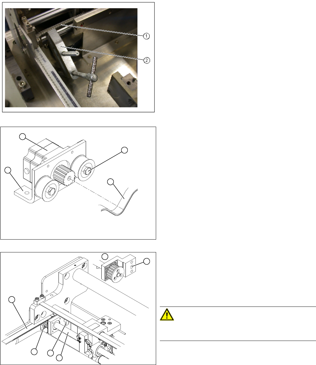
► Fix all 3 recirculating spindles (1) with suitable screw
clamps (2), so that these can not twist out of position
and affect the parallelism.
► The screw clamps rest on the lower edge of the
mounting tub.
► Loosen the eccentric axle (1) on the deflection pulley
and relieve the tension on the drive toothed belt (2).
► Loosen the fastening screws on the mount (3) and
then lift out the stepping motor (4). This makes it eas
-
ier to feed in the drive toothed belt, later on.
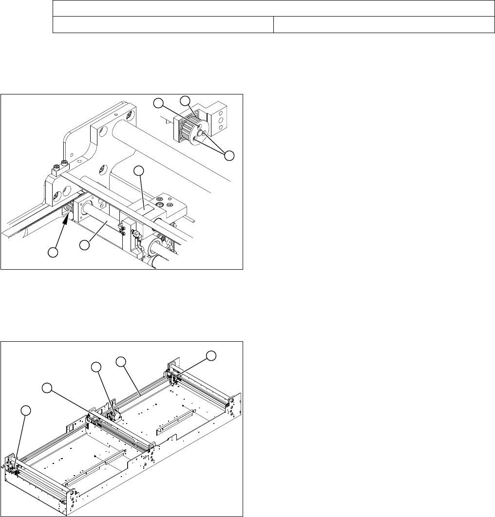
► Remove the screw (1) fastening the recirculating
spindle plus flange to the base.
(Item 5 shows the view from behind)
► Pull the spindle (2) out of the hole, the drive toothed
belt (3) can now be removed via the toothed
wheel (4).
CAUTION!
Make sure that the screw clamps used as an anti-twist
lock are fixed securely.
► Remove the complete drive toothed belt from the ma
-
chine.
4
1
3
2
1
1
5
4
3
2
Service Work
Modular PCB Conveyor System 3.4.2 Replacing the Stepping Motor of the Width Adjustment System [00367174-
76 Service Manual (internal version) SIPLACE HF and X Series
► Tension the drive toothed belt.
Position the measuring point of the belt tension device at the strand center in placement area 1 of
the drive toothed belt.
► Set the tension of the drive toothed belt according to the following values.
3.4.1.1
3.4.1.1 Restoring the Parallelism of the Adjustment Unit
Restoring the Parallelism of the Adjustment Unit
If a recirculating spindle has still twisted out of position with an adjustment unit (preventing the conveyor
from running parallel), the following fix can be performed:
3.4.2
3.4.2 Replacing the Stepping Motor of the Width Adjustment System [00367174-xx]
Replacing the Stepping Motor of the Width Adjustment System [00367174-xx]
Overview
Belt tension- width adjustment
Toothed belt for the drive 30 Hz +/- 2 Hz
► Open the three screws (2) fastening the toothed
wheel (1).
The recirculating spindle (3) and adjustment unit (4)
can now be rotated by hand (hold the toothed wheel
in place and turn the recirculating spindle).
► Measure the distance of a fixed adjustment unit to the
fixed conveyor edge.
► Rotate the loose recirculating spindle (3) until the ad
-
justment unit (4) is set to this value.
► Fix this position with the 3 fastening screws (2) on the
toothed wheel (1).
1
1
2
4
3
2
1. Width adjustment stepping motor
2. Toothed belt for the drive
3. Adjustment unit 1, 2 and 3
3
3
1
3
2