00195655-04_SM_X-Series_FSE_en.pdf - 第104页
Service Work TwinHead 3.7.1 Replacing the TwinHead Hoses 104 Service Manual (internal ver sion) SIPLACE HF and X Series ► Fix the elbow lightly into place with the fastening screw (1) . Now carefully move the elbow so th…
Service Work
3.7.1 Replacing the TwinHead Hoses TwinHead
Service Manual (internal version) SIPLACE HF and X Series 103
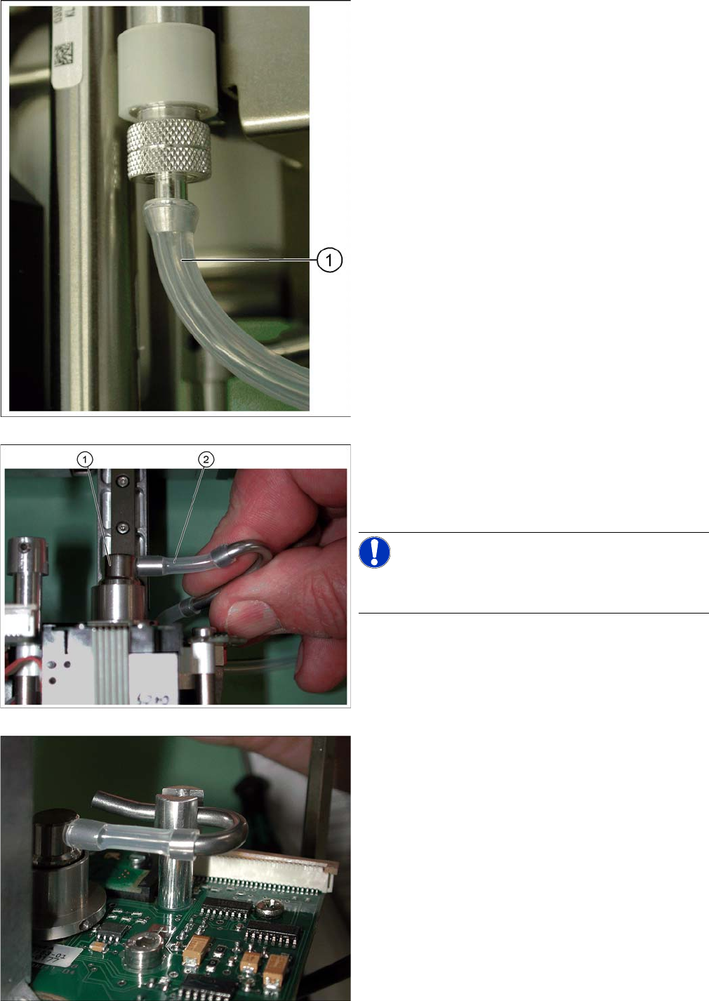
► Disconnect the long hose (1) at the top.
► Disconnect the short hose (2) from the rotary supply
(1) .
► Replace the short hose at the elbow with a new one.
This is 26 mm long.
NOTICE!
Fit the hoses approx. 4
-
5 mm onto the respective con
-
nections.
► Fit the short hose for the elbow onto the rotary supply.
► Place the elbow into its holder.
Service Work
TwinHead 3.7.1 Replacing the TwinHead Hoses
104 Service Manual (internal version) SIPLACE HF and X Series
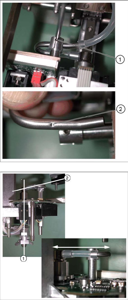
► Fix the elbow lightly into place with the fastening
screw (1).
Now carefully move the elbow so that the screw en
-
gages in the notch (2).
► Move the short hose between the elbow and the rota
-
ry supply.
The rotary supply and therefore the Z axis must be
positioned in the center of their guidance (1).
Press the hose against the connection more or pull it
away slightly, until the axis is centered properly.
An off-center position of the Z axis can change the
force ratios and lead to placement errors.
In addition, the short hose must be run
horizontally (2) between the elbow and the rotary
supply.
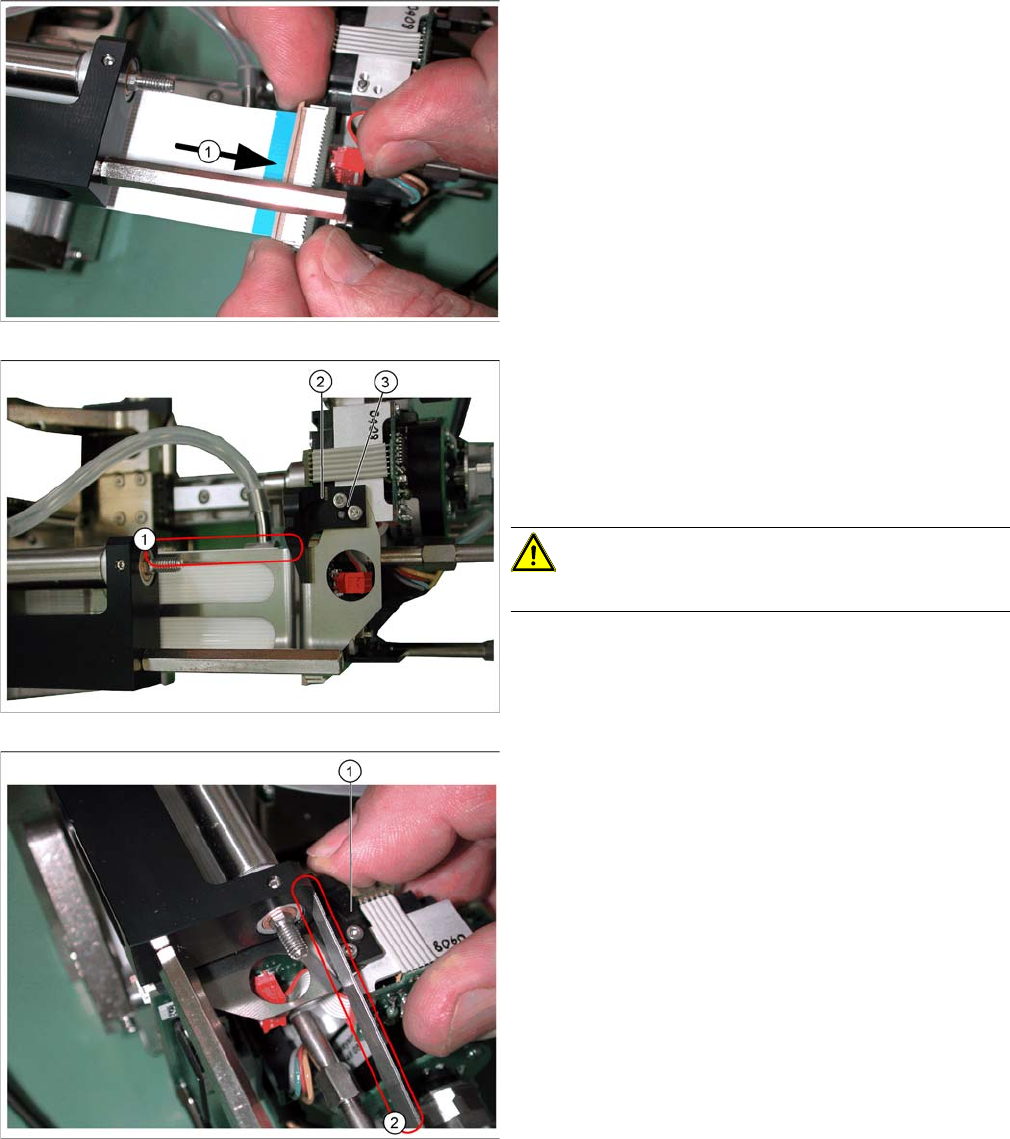
► After successfully adjustment, tighten the screw fas
-
tening the elbow.
► Reconnect the long hose at the top.
Service Work
3.7.1 Replacing the TwinHead Hoses TwinHead
Service Manual (internal version) SIPLACE HF and X Series 105
► Reconnect the flat ribbon cable connector (1).
► Place the flat ribbon baffle on the flat ribbon cable.
► Place the return unit stopper (2) onto the flat ribbon
baffle.
► Insert the two screws (3) into the stopper.
► Align the flat ribbon baffle to the flat ribbon cable.
CAUTION!
The baffle and cable must run parallel to one another (1)!
► Move the Z axis upwards.
► Insert the feeler gauge 0.6 mm (2) next to the stopper
(1).
► Tighten the screws fastening the stopper.
► Extract the feeler gauge.