00195655-04_SM_X-Series_FSE_en.pdf - 第39页
Service Work 3.3.1 Replacing the Trailing Cable Gantries Service Manual (internal ver sion) SIPLACE HF and X Series 39 Overview Version 1 from B-079 1. Head boar d with digital Vision board assemb ly [03017836-xx] 2. Tra…
Service Work
Gantries 3.3.1 Replacing the Trailing Cable
38 Service Manual (internal version) SIPLACE HF and X Series
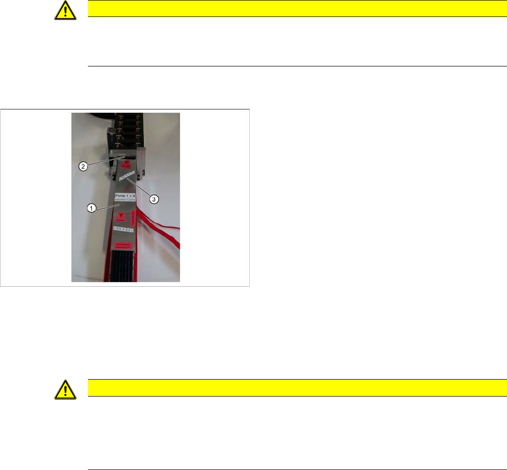
► Mark the pneumatic hoses through the holes (4) in the gauge. Observe the position labeled X hose.
► Use the hose pliers to cut the pneumatic hoses at the marked position. The pneumatic hoses can
now be run inside the pneumatic distributor, with the correct curvature.
► Observe the designation for the respective gantry on the gauge (1) (gantry 1+3 or gantry 2+4). Se
-
lect the correct gauge.
► Place the stopper edge (2) of the gauge (see mark labeled edge for clamp X +Y on the gauge) at the
edge of the clamp for the Y axis.
► Mark the pneumatic hoses through the holes (3) in the gauge.
► Use the hose pliers to cut the pneumatic hoses at the marked position. The pneumatic hoses should
now have the correct length and can be connected to the severed pneumatic hoses in the machine
base.
CAUTION
Mark the correct position!
► Observe the position labeled X hose.
► Observe the position marked machine inside on the gauge.
Shortening the Y hoses to the pneumatic distributor in the
machine base
1. Gauge for shortening the hoses
2. Stopper edge at the machine base clamp
3. Hose marking
CAUTION
Mark the correct position!
► Observe the position labeled Y hose.
► To ensure that they have the correct length, cut the pneumatic hoses at the marking labeled
"Y hose". If the pneumatic hoses are cut too short, you will have to discard the entire trail
-
ing cable.
Service Work
3.3.1 Replacing the Trailing Cable Gantries
Service Manual (internal version) SIPLACE HF and X Series 39
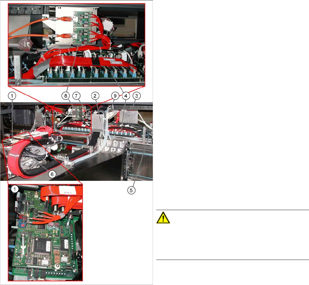
Overview
Version 1 from B-079
1. Head board with digital Vision board assembly
[03017836-xx]
2. Trailing cable console
3. Power track chain
4. Trailing unit interface gantry
5. Pneumatic hoses to the pneumatic distributor (in the
machine base)
6. Gantry distributor
7. Gantry Interface
8. Hotlink filter [03010670-xx]
9. Connection piece for cooling tubes to Y motor
► The flat ribbon cable and the camera cable are run
from the head board (1) via the trailing cable console
(2) and the power track chain (3) to the gantry inter
-
face (7) and the trailing cable interface gantry (4).
The camera cable ends at the hotlink board (8).
► The pneumatic hoses are fed from the pneumatic dis
-
tributor (6), via the trailing cable console (2) and the
power track chain (3) to the gantry distributor in the
machine base.
► Disconnect the camera cable from the hotlink board
(8).
► Remove cable ties where necessary.
CAUTION!
Note the order in which the terminal connections are ar
-
ranged.
Label the press-fit connections to the flat ribbon cable
and the camera cable, for easier reconnection later.
► Disconnect the Y motor cooling tubes at the connec
-
tion pieces (9).
Service Work
Gantries 3.3.1 Replacing the Trailing Cable
40 Service Manual (internal version) SIPLACE HF and X Series
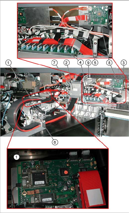
Version 2 after B-079
See also
3.3.1.7.2 Preparing the Trailing Cable [ ➙ 37]
3.3.1.4 Handling the Hose Unlocking Tool [03047090-xx] [ ➙ 24]
1. Vision board spread spectrum (VBSX) assembly
[03054634-xx]
2. Trailing cable console
3. Power track chain
4. Trailing unit interface gantry
5. Pneumatic hoses to the pneumatic distributor (in the
machine base)
6. Gantry distributor
7. Gantry Interface
8. Vision hotlink adapter VHA assembly [03054633-xx]
9. Connection piece for cooling tubes to Y motor