00195655-04_SM_X-Series_FSE_en.pdf - 第81页
Service Work 3.4.6 Replacing the Actuator for the Width Adjustment System [0 0355533-xx] Modular PCB Conveyor System Service Manual (internal ver sion) SIPLACE HF and X Series 81 3.4.6 3 . 4 . 6 R e p la c in g t h e A c…
Service Work
Modular PCB Conveyor System 3.4.5 Replacing the Proximity Switch for the Adjustment System [00369018-xx]
80 Service Manual (internal version) SIPLACE HF and X Series
3.4.5
3.4.5 Replacing the Proximity Switch for the Adjustment System [00369018-xx]
Replacing the Proximity Switch for the Adjustment System [00369018-xx]
Parts
▪ Proximity switch for adjustment unit 1 [00369018-xx]
▪ Proximity switch for adjustment unit 2 [00369019-xx]
▪ Proximity switch for adjustment unit 3 [00365573-xx]
Overview
The proximity switch serves as a signal for controlling the pneumatic valve of the adjustment unit. Once
the switching point has been reached, the conveyor edge is connected via the short-stroke cylinder.
Removal/Installation
The switching point is set at the actuator on the conveyor edge:
► Move the adjustment unit until it is under the conveyor edge.
► Place a 2/10 mm distance gauge on the adjustment unit, press the actuator onto the distance gauge
and tighten the screw.
► Use the SITEST program to calibrate the conveyor edges.
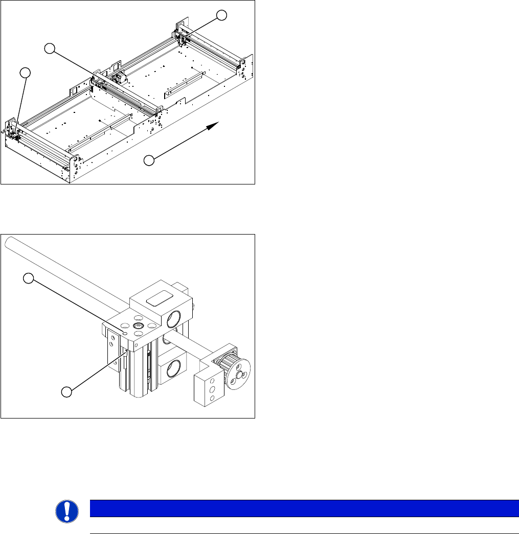
1. Adjustment unit 1
2. Adjustment unit 3
3. Adjustment unit 2
4. Transport direction
► Move the PCB conveyor to the position which gives
you best access to the adjustment system.
► Move the Y gantries into the area outside the PCB
conveyor.
► Switch off the machine and secure it to prevent unau
-
thorized reactivation.
► Switch off the compressed air supply.
3
4
1
2
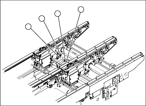
► Loosen the grub screw on the clamping device (1)
and unthread the connection cable as far as the con
-
version board of the assembly tub.
► Fit the new proximity switch and reconnect the sys
-
tem to the electrical system.
► Fix the proximity switch with the grub screw. The
proximity switch must be level with the adjustment
unit housing (2).
2
1
NOTICE
This setting must be performed at all conveyor edges.
Service Work
3.4.6 Replacing the Actuator for the Width Adjustment System [00355533-xx] Modular PCB Conveyor System
Service Manual (internal version) SIPLACE HF and X Series 81
3.4.6
3.4.6 Replacing the Actuator for the Width Adjustment System [00355533-xx]
Replacing the Actuator for the Width Adjustment System [00355533-xx]
Overview
Removal/Installation
► Move the PCB conveyor to the position which gives you best access to the actuator.
► Move the Y gantries into the area outside the PCB conveyor.
► Switch off the machine and secure it to prevent unauthorized reactivation.
► Switch off the compressed air supply.
► Loosen and remove the screw fastening the actuator.
► Insert the new actuator and screw in loosely.
► The switching point is set at the actuator on the conveyor edge.
Move the adjustment unit under the conveyor edge.
► Place a 2/10 mm distance gauge on the adjustment unit, press the actuator onto the distance gauge
and tighten the screw.
► Calibrate the conveyor edges.
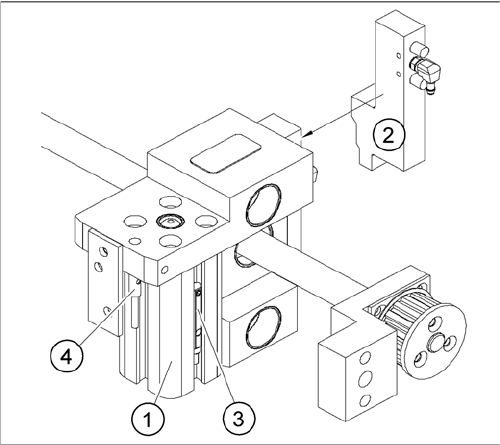
1. Actuator
2. Driver
3. Adjustment unit
4. Proximity switch for adjustment unit
1
4
3
2
Service Work
Modular PCB Conveyor System 3.4.7 Width Adjustment Unit
82 Service Manual (internal version) SIPLACE HF and X Series
3.4.7
3.4.7 Width Adjustment Unit
Width Adjustment Unit
3.4.7.1
3.4.7.1 Setting the Proximity Switch on the Adjustment Unit
Setting the Proximity Switch on the Adjustment Unit
Overview
Removal/Installation
► When installing the proximity switch, make sure that this is level with the adjustment unit housing.
► The switching point is set via the actuator on the conveyor side.
► Move the adjustment unit under the conveyor side, then loosen the actuator using the screw.
► Place the distance gauge 0.2 mm on the adjustment unit, press the actuator against the gauge and
fix with the screw.
► Actuators on all conveyor sides have to be checked and adjusted where necessary.
► You then need to calibrate the conveyor sides with the software.
Overview of the proximity switches on the adjustment unit
for width adjustment
1. Short-stroke cylinder
2. Solenoid valve
3. Proximity switch for pneumatic cylinder (for "locking
pin up" recognition)
4. Proximity switch for adjustment unit(for conveyor side
recognition)
▪ The proximity switch (3) serves as a signal for con
-
trolling the pneumatic valve of the adjustment unit.
Once the switching point "conveyor side present" has
been reached, the conveyor side is connected via the
pneumatic valve.