00195655-04_SM_X-Series_FSE_en.pdf - 第12页
Introduction Preparatory Work... 1.1.9 Classification of the Optical Systems 12 Ser vice Manual (internal ver sion) SIPLACE HF and X Series Lockout attachment Z-IS/SPE-1TE [03123101-xx] X Series and ol der: Example: Atta…
Introduction
1.1.9 Classification of the Optical Systems Preparatory Work...
Service Manual (internal version) SIPLACE HF and X Series 11
1.2
1.2 Preparatory Work...
Preparatory Work...
Purpose and Scope
Before performing any preventive maintenance work, conversion work or service work, a procedure of
locking and tagging must be followed and warning signs must be attached if not stated otherwise. If it is
not necessary to switch off the machine, it is explicitly mentioned.
The procedure, when followed correctly, eliminates the possibility of an employee being injured.
Description
Whenever it becomes necessary to isolate, control and release energy, the following procedure is to be
followed.
► Notify affected employees.
► Switch off the machine and all additional devices. Carry out all normal stopping procedures:
⇨ Press the STOP button.
⇨ Shut down the station computer.
⇨ Switch the machine off at the main switch.
► Isolate the machine from all its energy sources:
⇨ Shut off the compressed air supply.
⇨ Shut off the main power supply.
► Lock out the machine.
⇨ Attach a lock wherever possible (e.g. to the main power switch).
NOTICE
Additional safety measures
These procedures represent the minimum lock/tag out requirements for the machine during
preventive maintenance work and service work. Any additional safeguards needed to complete
work safely can be specified by facilities supervision, the safety officer, the safety committee
and the health department.
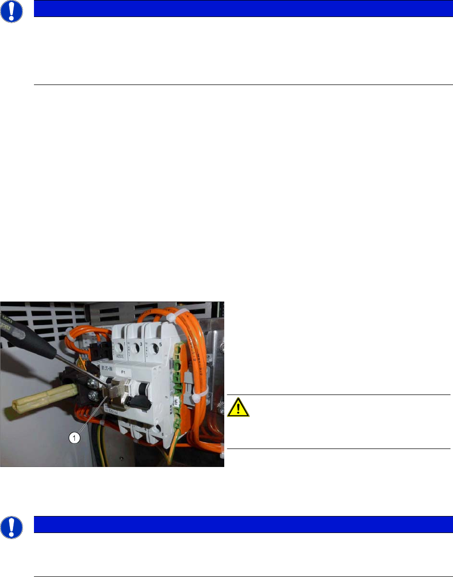
Attaching the lockout attachment Z-IS/SPE-1TE
[03123101-xx]
Example: Securing the machine with a lockout at
-
tachment
The lockout attachment can prevent the machine
from being switched on inadvertently.
► Switch off the machine.
► Set the circuit breaker to OFF.
CAUTION!
The lockout attachment may only be attached when
the machine is switched off!
► Attach the lockout attachment (1) to the circuit
breaker.
► Secure the circuit breaker with a padlock.
NOTICE
Lockout attachment in the service box of your machine
On machines that are delivered from June 2016, the lockout attachment [03123101
-
xx] is lo
-
cated in the service box.
Introduction
Preparatory Work... 1.1.9 Classification of the Optical Systems
12 Service Manual (internal version) SIPLACE HF and X Series
Lockout attachment Z-IS/SPE-1TE [03123101-xx]
X Series and older: Example: Attaching a padlock to the motor contactor
► Attaching warning signs:
If a machine can be locked, it must be.
However, there are situations where energy isolating devices cannot accommodate locks. In these
cases, the energy isolating devices must be tagged to warn employees that the machine is de-ener
-
gized for servicing. The tag or label must be securely fastened, it must be placed in a position visible
to all and it may only be removed by the person who attached it.
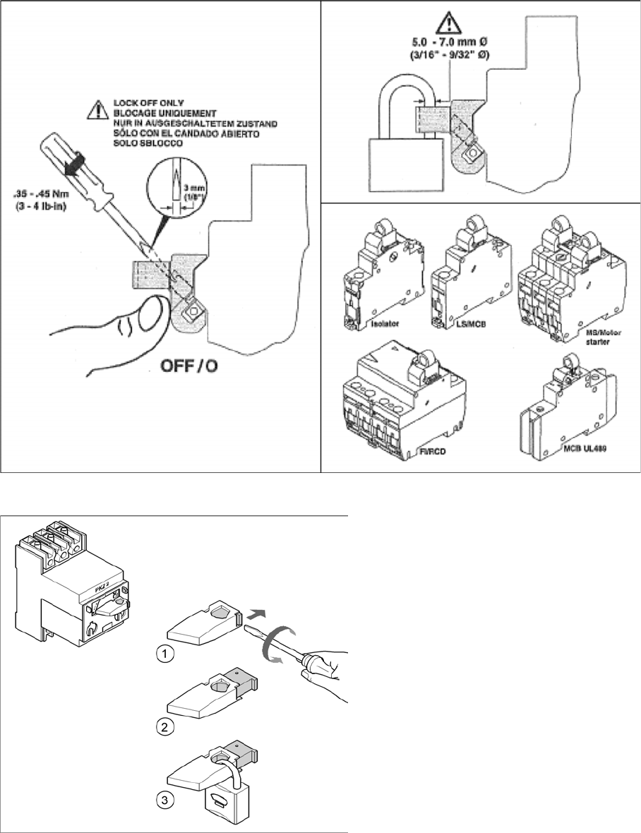
Attaching a padlock to the motor contactor
Example: Attaching a padlock to the motor
contactor
► Turn the operating lever (1) counterclock
-
wise.
► Use the screwdriver to push the locking
lug (2) out of the operating lever (1).
► Secure the operating lever with a padlock
(3).

Introduction
1.1.9 Classification of the Optical Systems Preparatory Work...
Service Manual (internal version) SIPLACE HF and X Series 13
► Release of stored energy:
Stored energy in the compressed air supply or electrical energy in electrolytic capacitors must be
released by appropriate means.
After switching off the machine, wait until the voltages and the compressed air have discharged, so
that work can be performed without any risk.
DANGER - Checking the power supply for absence of voltage
► Testing the lock out:
The lock can be easily tested by pressing the START button.
The following steps must be taken to restore the machine to operation.
► Check the working area. Authorized employees should remove all of their tools and reinstall all safety
features.
► Notify all affected employees.
► Before removing even one lock or tag, inform all workers in the affected area that the machine is
going to be restarted.
► Remove all locks/tags.
Every authorized employee must remove his own lock and shut it away.
► Turn the machine on. Make sure that authorized staff check the equipment in operation to ensure
that repairs were performed correctly
Testing
Service personnel may test circuits by energizing them briefly without suspending the Lock Out / Tag
Out Procedure. This may only be done when no other work is being performed by any other person on
the equipment being tested.
It is extremely important that all remote START switches be tagged with the "Do Not Operate" tag to pre
-
vent inadvertent operation of the equipment during these periods.
Responsibilities
▪ It shall be the responsibility of the maintenance and service personnel to make sure this procedure
is adhered to.
▪ It shall be the responsibility of the maintenance and service personnel's immediate supervisor to in
-
struct his personnel on this procedure.
▪ It shall be the responsibility of the Safety Officer to administer the Lock Out / Tag Out Procedure.
DANGER
Checking for absence of voltage!
► Before you start working, check the power supply for absence of voltage and observe the
waiting times!