00195655-04_SM_X-Series_FSE_en.pdf - 第86页
Service Work C&P20 Placement Head 3.5.1 Replacing the E/D Transformer (Collec tor Ring) - FSE 86 Ser vice Manual (internal ver sion) SIPLACE HF and X Series Removing the E/D transformer ► The upper side of the E/D tr…
Service Work
3.5.1 Replacing the E/D Transformer (Collector Ring) - FSE C&P20 Placement Head
Service Manual (internal version) SIPLACE HF and X Series 85
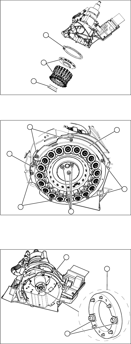
Removing the star
1. Hold circuit - vacuum unit
2. Star, complete with E/D transformer
3. Raceway
► Remove the hold circuit vacuum unit (1).
► You can now access the star (2).
1
3
2
► Loosen the 6 fastening screws (2) holding the race
-
way (1).
► The raceway is fixed to the Z axis position with pins
(3). Gently lever the raceway off with a suitable
screwdriver.
⇨ The raceway can not be removed and will remain
hanging from the star. Carefully place the raceway
onto the segments.
► Loosen the 3 fastening screws (4) holding the star
and carefully lift these out of the star carrier.
⇨ Note the different lengths of the 3 fastening screws
(4). Mark their installation positions.
⇨ The connection cable is long enough to remove
the star and E/D transformer and then disconnect
outside the star carrier.
► Disconnect the E/D transformer and place the entire
unit down on a suitable surface.
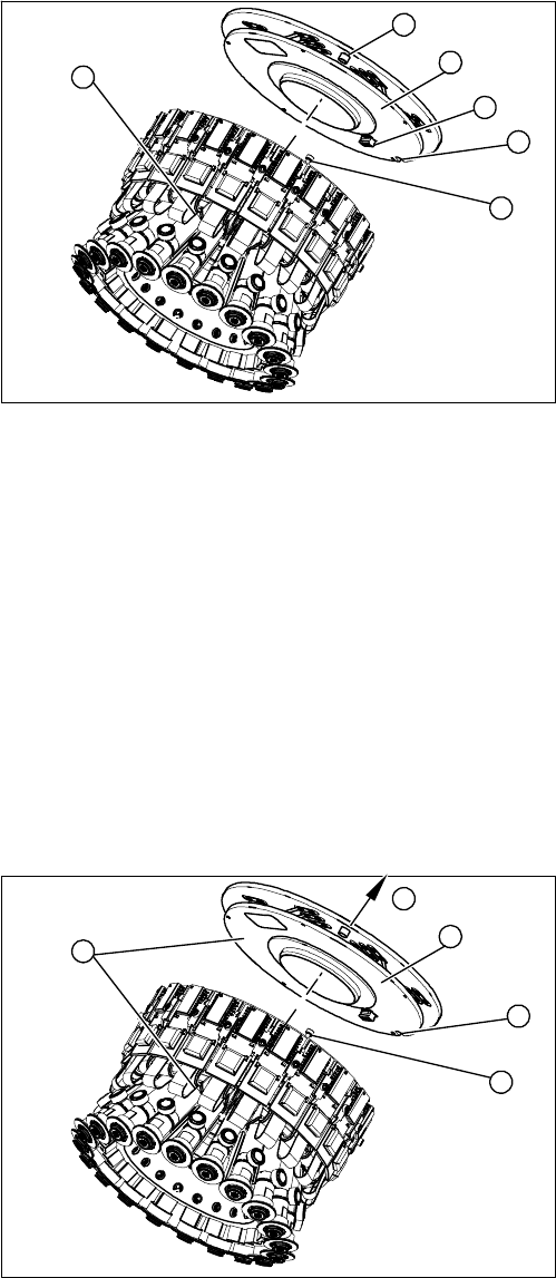
► Pull the smoothed distributor disc (1) off the motor
shaft (3) of the star drive. Take care of the O ring on
the motor shaft.
► Make sure that you do not lose the 4 O rings (2) on
the smoothed distributor disc!
► Clean the 4 O rings (2) (2 on each side) on the
smoothed distributor disc and grease them slightly
with Unisilikon.
► Clean the O ring (3) on the motor shaft and grease
slightly with Unisilikon.
► Attach the smoothed distributor disc to the rotary ax
-
is.
2
2
1
4
3
2
3
1
2
Service Work
C&P20 Placement Head 3.5.1 Replacing the E/D Transformer (Collector Ring) - FSE
86 Service Manual (internal version) SIPLACE HF and X Series
Removing the E/D transformer
► The upper side of the E/D transformer (2) has a service opening (1), through which you can loosen
the 5 fastening screws. Simply turn the upper section over the individual screws and loosen these in
succession.
► Attention:
Do not loosen the index screw (4).
► Carefully pull the E/D transformer (2) upwards and out of the connection (6) on the star (5).
⇨ The star has an index screw (4), which enables you to fit the E/D transformer in the correct posi
-
tion.
► Fit the E/D transformer (2) so that the index screw is aligned with the groove in the E/D transformer.
⇨ Make sure that the connector (6) engages correctly.
► Fix the E/D transformer with the 5 fastening screws, through the service opening (1).
Fitting the E/D transformer
1. Service opening
2. E/D transformer
3. Groove for index screw
4. Index screw
5. Star
6. Connectors
6
1
5
4
3
2
► Turn the E/D transformer (2) so that the index screw
(4) is aligned above the groove (3) in the E/D trans
-
former.
► Fit the star with E/D transformer (5) carefully with the
pins on the motor shaft into the star carrier.
► Attach the connection cable to the E/D transformer
(2).
► Fit all the components you removed. Follow the in
-
structions in the relevant sections of this service man
-
ual.
1
5
4
3
2
Service Work
3.5.2 Settings the C&P20 (FSE) Jaws C&P20 Placement Head
Service Manual (internal version) SIPLACE HF and X Series 87
3.5.2
3.5.2 Settings the C&P20 (FSE) Jaws
Settings the C&P20 (FSE) Jaws
3.5.2.1
3.5.2.1 General
General
Contents of service kit for setting C&P20 jaws [03058847-01]:
▪ Jaw setting gauge with 2x hexagon socket-head screw M2.5x12 mm [03045455-01]
▪ 4 x feeler gauge 0.01 mm [03058840-01]
▪ Feeler gauge 0.04 mm [03058839-01]
▪ Hose piece D12 length 20 mm [03058392-01]
▪ Rubber hose to protect the component sensor
▪ 10x dead indexing plate [03013091-01]
Tools required:
▪ Phillips screwdriver with torque limiter, set to 35 Ncm
▪ Head mounting rack
▪ Hexagon socket-head wrench
NOTICE
SIPLACE Service
This setting may only be performed by the SIPLACE service team!
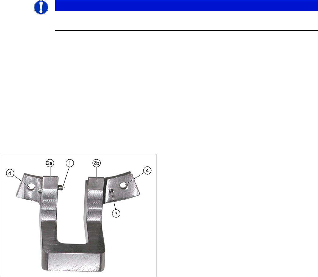
Jaw setting gauge
1. Side stop for jaws
2. 2a and 2b: contact surfaces for jaws
3. Centering pins for accurate setting to raceway
4. Gauge fixture on raceway (screws --> M2.5x12 mm)