00195655-04_SM_X-Series_FSE_en.pdf - 第55页
Service Work 3.3.5 Replacing the X Drive (Primary) [03039726- xx] Gantries Service Manual (internal ver sion) SIPLACE HF and X Series 55 1. Insert 4 x dismantling screws 2. 4 x l ock scr ews M4x6 0 ► On each of the 4 sid…
Service Work
Gantries 3.3.5 Replacing the X Drive (Primary) [03039726-xx]
54 Service Manual (internal version) SIPLACE HF and X Series
Removal
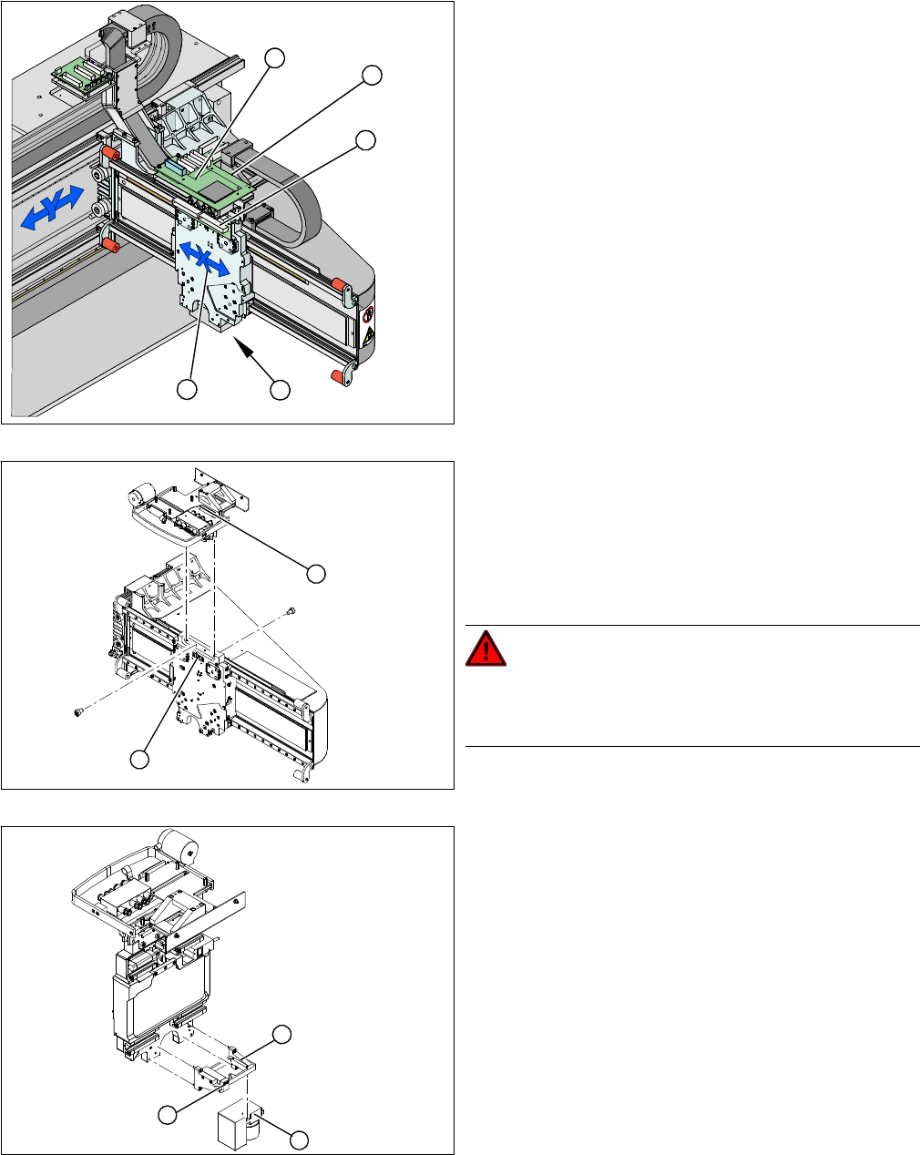
1. X drive (primary) with head mount
2. X mount with trailing cable
3. Head adapter board
4. Mount with PCB camera
5. Head board
► Dismantle the placement head.
► Remove the head adapter board (3). The X mount fix
-
tures (2) are now accessible.
► Unplug the following cables from the head board (5)
and remove them from the X mount (2):
⇨ X motor cable
⇨ The Y axis incremental encoder
⇨ Temperature sensor
► Unplug the proximity switch cable (2) and pull it for
-
wards, out of the head mount.
► Undo the 8 screws (4 x at front/ 4x at back) fastening
the X mount (1) and pull these up and out, together
with the trailing cable.
► Fasten the X mount at a suitable point.
DANGER!
Make sure that the flat ribbon cable and the pneumatic
hoses are not rubbed against any parts or folded. Look
out for sharp edges.
► Undo the 4 screws fastening the PCB camera mount
(1). Remove the complete unit, including PCB cam
-
era (3) and damping bracket (2).
► Fix the mount (1) to a suitable point on the machine
base. Take care not to damage the camera.
5
5
1 4
3
2
2
1
1
3
2
Service Work
3.3.5 Replacing the X Drive (Primary) [03039726-xx] Gantries
Service Manual (internal version) SIPLACE HF and X Series 55
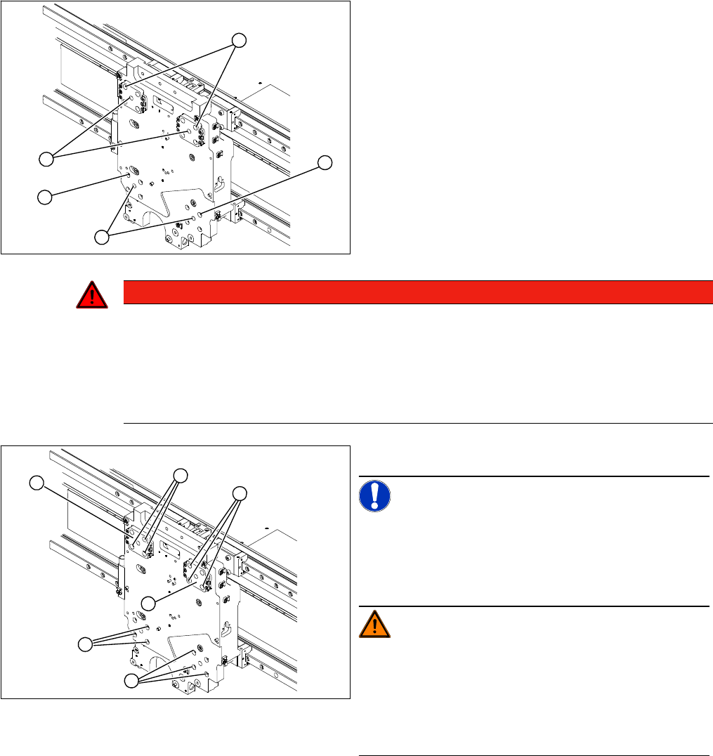
1. Insert 4 x dismantling screws
2. 4 x lock screws M4x60
► On each of the 4 sides, insert 1 dismantling screw (1)
and tighten as far as the stopper.
► Remove one fastening screw (2) from each of the 4
sides.
► Replace this fastening screw with a M4x60 lock
screw in each case. This prevents the motor from fall
-
ing down when pressure is applied to it.
1
2
2
1
2
DANGER
Risk of fatal injuries through trapped limbs.
For safety, place a piece of foam between the X drive and the magnetic strip.
For additional safety, keep the 4 dismantling screws in place until the X drive has been removed
from the machine.
► Once the X drive is out of the vicinity of the strong magnetic field, it can be removed from
the machine. Loosen the 4 lock screws to remove it.
► Undo the remaining 12 fastening screws (1).
NOTICE!
Note the screw lengths!
Make a note of the different screw lengths. These will
need to be correctly replaced later. Mark the positions of
the individual screws.
WARNING!
Do not undo or loosen the screws on the Z axis compen
-
sation (2), which have been secured with locking varnish.
Screw in the dismantling screws in turn, so that the X
drive is evenly pushed away from the magnetic field of
the magnetic strip. The X drive is now held by the 4 lock
screws.
1
1
1
2
2
M4 x 8
M4 x 18
M4 x 14
1
Service Work
Gantries 3.3.5 Replacing the X Drive (Primary) [03039726-xx]
56 Service Manual (internal version) SIPLACE HF and X Series
Installation
► Now fit 3 fastening screws on each side. Observe the different screw lengths.
► Remove the lock screws and fit the fastening screws in their place.
► Tighten all fastening screws crosswise with a torque wrench (2.9 N).
► Install the PCB camera.
► Check the gap between the X drive and the magnet cover with a 0.4 mm thickness gauge.
► To do this, place the thickness gauge between the X drive and the magnet cover and then push the
X drive back and forth along the entire length. Make sure none of the parts jam.
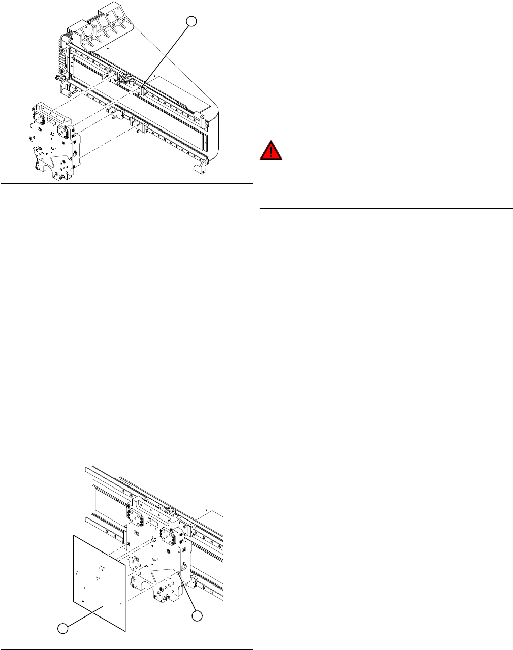
Closing drillings for individual head configurations
The drillings used to fasten the head vary between the different head configurations. Those which are
not needed must be closed. This prevents the cooling air from escaping!!
▪ Template for C&P12/6 head [03011690-xx]
▪ Template for C&P20 head [03011694-xx]
▪ Template for TwinHead [03011693-xx]
▪ Grub screws M 4x6-ST [00309422-xx]
► Clean the contact surface of the guide trolley (1) with
a dressing stone (oil stone). Then wipe the contact
surface clean with ethanol.
► Screw the dismantling screws fully into each side of
the new X drive.
► Place the foam rest on the magnetic strip.
► Lift the new X drive up to the guide trolley and fasten
the X drive with the M4x60 lock screws.
► Remove the foam rest.
DANGER!
Risk of fatal injuries through trapped limbs.
Make sure that you do not trap any limbs between the X
drive and the magnetic strip.
1
► Clean all drillings with a pipe cleaner and ethanol, to
remove any adhesive residues.
► Position the relevant template on the centering pins
of the head mount and attach the template.
► Use the holes in the template to screw the grub
screws (with Loctite 241) into the head mount.
► These grub screws must be level with the surface of
the head mount (countersunk).
1
2