00195655-04_SM_X-Series_FSE_en.pdf - 第60页
Service Work Gantries 3.3.7 Replacing the Y Axis Scale [03005490-xx] 60 Ser vice Manual (internal ver sion) SIPLACE HF and X Series 3.3.7 3 . 3 . 7 R e p la c in g t h e Y A x is S c a le [ 0 3 0 0 5 4 9 0 - x x ] Replac…
Service Work
3.3.6 Replacing the X Axis Incremental Encoder Gantries
Service Manual (internal version) SIPLACE HF and X Series 59
Removal
Installation
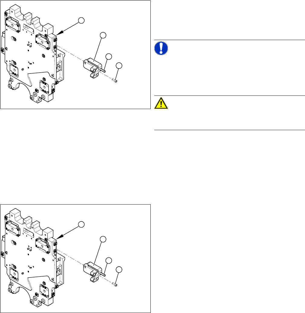
1. Head plate - front view
2. Incremental encoder
3. Three fastening screws
4. Grub screw (secured with Loctite No. 241)
NOTICE!
Grub screw on the incremental encoder
If the incremental encoder is installed on the head plate
of a CFK 04 or 06 gantry, the grub screw is without func
-
tion. Do not loosen or tighten this grub screw.
CAUTION!
HF – CFK02 gantry
Refer to the relevant guide for the CFK02 gantry.
► Unthread the connection cable as far as the incre
-
mental encoder (2).
► Loosen the three screws (3) fastening the incremen
-
tal encoder (2) of the X axis and carefully lift off the
incremental encoder.
3
4
1
2
► Clean the reading surface of the incremental encoder
with a cloth and ethanol or with a cleansing tip.
► Loosely fasten the incremental encoder (2) with three
fastening screws (3).
► The incremental encoder must be aligned with a
0.75 mm gap (for the old read head [03020588-xx]
0.4 mm) to the scale. Use the corresponding thick
-
ness gauge (plastic).
3
4
1
2
Service Work
Gantries 3.3.7 Replacing the Y Axis Scale [03005490-xx]
60 Service Manual (internal version) SIPLACE HF and X Series
3.3.7
3.3.7 Replacing the Y Axis Scale [03005490-xx]
Replacing the Y Axis Scale [03005490-xx]
Please also observe the technical information "Overview of Scales and Read Heads" [DE: TI2014-
05D11] [EN: TI2014-05E11].
Tools
▪ Scale - adhesive device set (HF/ X-Series) [00377013-xx]
▪ Double-sided adhesive strip - Scotch Y-9460 [00343774-xx]
▪ Protective sheet 12mm wide [00378511-xx]
▪ Ethanol
▪ Protective gloves (provided with set)
Prior checks
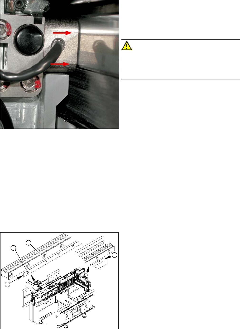
Casting marks on the incremental encoder
► You must set the exact height to the scale.
► Align the incremental encoder, using the two casting
marks (arrows), which mark the read area.
► Tighten the fastening screws.
► Reconnect to the electricity supply (X15 or X24).
CAUTION!
Check how the cables are run!
Make sure that the axes can be moved without damaging
the cables.
Fasten the cables with cable ties.
► Move the gantry into the end stopper and check that
the bumper does not come into contact with the ca
-
ble.
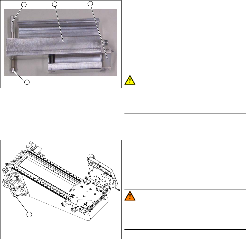
► Check whether there is a drill hole (1) on the machine
base. If not, you will need to mark the start and end
positions (2) of the old scale (3) with a scribing iron.
► Check the length of the installed scale. If this is short
-
er than the replacement scale, you will need to fix the
new scale from position 1 or 3 onwards with adhe
-
sive.
2
1
3
2
Service Work
3.3.7 Replacing the Y Axis Scale [03005490-xx] Gantries
Service Manual (internal version) SIPLACE HF and X Series 61
Checking the adhesive device
Overview
1. Press roller
2. Adhesive device (viewed from below)
3. Fixing pin
4. Screw
► Check the setting of the press roller (1).
► Place the adhesive device (2) and the press roller flat
onto the table.
► Place a plastic sheet (0.2 mm thickness) under the
press roller. Make sure that the press roller lies flat on
the plastic sheet.
CAUTION!
Set the fixing pin correctly
The fixing pin for the scale must be set so that it touches
the screw (4) and can guide the scale, without the latter
slipping out.
1
4
3
2
1. Y axis incremental encoder
► Loosen the three screws fastening the incremental
encoder (1) of the Y axis and carefully lift off the in
-
cremental encoder.
► Temporarily fix the incremental encoder to a suitable
place (e.g. with adhesive tape to the back of the gan
-
try).
WARNING!
STRONG MAGNETIC FIELDS!
Always follow the special safety instructions when work
-
ing in the vicinity of powerful magnetic fields, caused by
the permanent magnets (3).
1