00195655-04_SM_X-Series_FSE_en.pdf - 第21页
Service Work 3.2.1 Fitting the One-Piece Cove rs for the X-Series Measuring Eq uipment and Tools Service Manual (internal ver sion) SIPLACE HF and X Series 21 3 3 S e r v ic e W o r k Service Work 3.1 3 . 1 M e a s u r i…
Overview of the Modules
Serial Number of Module
20 Service Manual (internal version) SIPLACE HF and X Series
2.1
2.1 Serial Number of Module
Serial Number of Module
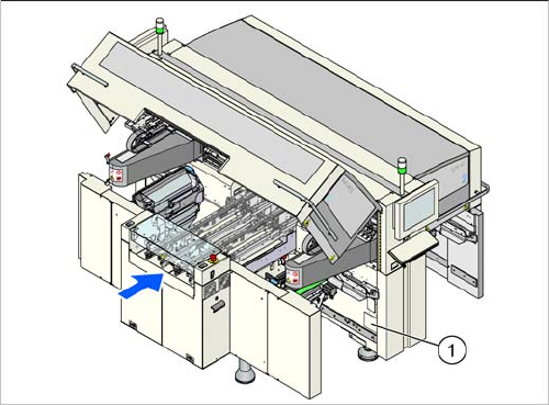
The serial number of your placement machine can be
found on the typeplate. This is located on the inside of lo
-
cation 1, at the side (1).
Service Work
3.2.1 Fitting the One-Piece Covers for the X-Series Measuring Equipment and Tools
Service Manual (internal version) SIPLACE HF and X Series 21
3
3 Service Work
Service Work
3.1
3.1 Measuring Equipment and Tools
Measuring Equipment and Tools
For more information about the measuring equipment and tools used, refer to the service section of our
homepage at www.siplace.com.
3.2
3.2 Basic Machine
Basic Machine
3.2.1
3.2.1 Fitting the One-Piece Covers for the X-Series
Fitting the One-Piece Covers for the X-Series
► Remove all foil from the inside of the protective covers.
► Remove one screw per Schmersal switch on the rucksack and press this downwards.
This is necessary in order to avoid potential problems when fitting the covers.
► Fit two gas pressure absorbers per protective cover.
► Fix the protective covers to the machine with bolts.
Aligning and fastening the covers:
► Loosen 2x screws on the hinge of each cover and place a circlip underneath.
► Roughly align the cover with an angle bracket.
► Now align the covers precisely in relation to the rucksacks (right/left) and the contact points on the
substructure.
► Fix the cover hinges into place with the plate and 2 screws (side fixtures).
► Position the gas pressure absorbers onto the cover wings and secure these with the locking springs.
► Fit the ESD discharge strap for the cover with a screw (DIN7984 M8x12), a circlip and a plate to the
cover wings.
► Check the cover for correct functionality.
Setting the Schmersal switch:
► Refit the screw which fastens the Schmersal switch and was removed to take off the cover.
► Loosen the lower screws fastening the Schmersal switch and adjust these so that they are approx.
1 mm from the cover and positioned centrally to the cover plug.
► After alignment, align the hinge so that it is straight
and secure the fixture nuts with Loctite 241.
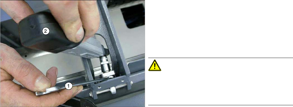
► Now tighten the nuts with a torque of 6 Nm. To do
this, place a fork wrench (1) over the inner nut and
hold this tight. Then tighten the outer nut with the
torque wrench (2) until the required torque is reached
(wrench will click).
CAUTION!
Do not tighten any more, otherwise you will set a different
torque!
If the covers are removed, use new nuts afterwards, to
prevent any damage.
Service Work
Gantries 3.3.1 Replacing the Trailing Cable
22 Service Manual (internal version) SIPLACE HF and X Series
3.3
3.3 Gantries
Gantries
3.3.1
3.3.1 Replacing the Trailing Cable
Replacing the Trailing Cable
3.3.1.1
3.3.1.1 Introduction
Introduction
This manual describes the installation and removal of the trailing cable for Siplace HF and X-Series ma
-
chines in their various versions.
This manual sometimes uses diagrams of the SIPLACE HF machine. However, this does not affect the
installation and removal for X-Series machines. If there are differences between the two machines types,
which need to be observed, this will be indicated on the diagrams.
3.3.1.2
3.3.1.2 Overview of SIPLACE HF Variants
Overview of SIPLACE HF Variants
Trailing cable HF
Depending on the arrangement of gantries, there are three different trailing cable types available for
SIPLACE HF machines.
▪ Trailing cable for HF machines at gantry 1 in a placement area with one gantry
HF gantry 1 or 3, HF3 gantry 3
– [03039706S01] Trailing cable analog 1P
▪ Trailing cable for HF machines in a placement area with two gantries and an uneven number
HF3 gantry 1
– [03039708S01] Trailing cable analog 2P U
▪ Trailing cable for HF machines in a placement area with two gantries and an even number:
HF3 Portal 4
– [03039709S01] Trailing cable analog 2P G
3.3.1.3
3.3.1.3 Overview of SIPLACE X4I/X Series Variants
Overview of SIPLACE X4I/X Series Variants
X series trailing cable up to machine serial number B-078
Depending on the arrangement of gantries, there are three different trailing cable types available for
SIPLACE X series machines.
▪ Trailing cable for X series machines in a placement area with one gantry:
X2 gantry 1/3, X3 gantry 3
– [03015419-03] Trailing cable digital 1P
▪ Trailing cable for X series machines in a placement area with two gantries and an uneven number:
X3 gantry 1 and X4 gantry 1/3
NOTICE
Downwards compatibility
These versions of the trailing cable can also be used with SIPLACE HF machines up to ma
-
chine number A-219, in conjunction with the "Trailing cable retrofit kit" [03046248-01]. This ret
-
rofit kit is included in the trailing cable spare parts set.
► Fit the new cable supports.
CAUTION
Conversion to a new trailing cable
Some of the machines up to number B-078 have been converted to accommodate the new trail
-
ing cable from number B-079.
► Before ordering the trailing cable, please compare the item numbers on your current ma
-
chine.
► The conversion of a customer machine involves significant costs and is only possible at the
SIPLACE headquarters.