F4000N_revD.pdf - 第102页
F4000N Series Operating Manual Section 7: Error M essages and Specifications Part # 562187N - 1 Rev . D Sep 2012 101 © 20 12 Fisnar Inc. 2.2 Ext. Con trol Connector: The pin assignments for the external control connector…
F4000N Series Operating Manual
Section 7: Error Messages and Specifications
Part # 562187N-1
Rev. D Sep 2012
100
© 2012 Fisnar Inc.
2. I/O Specifications
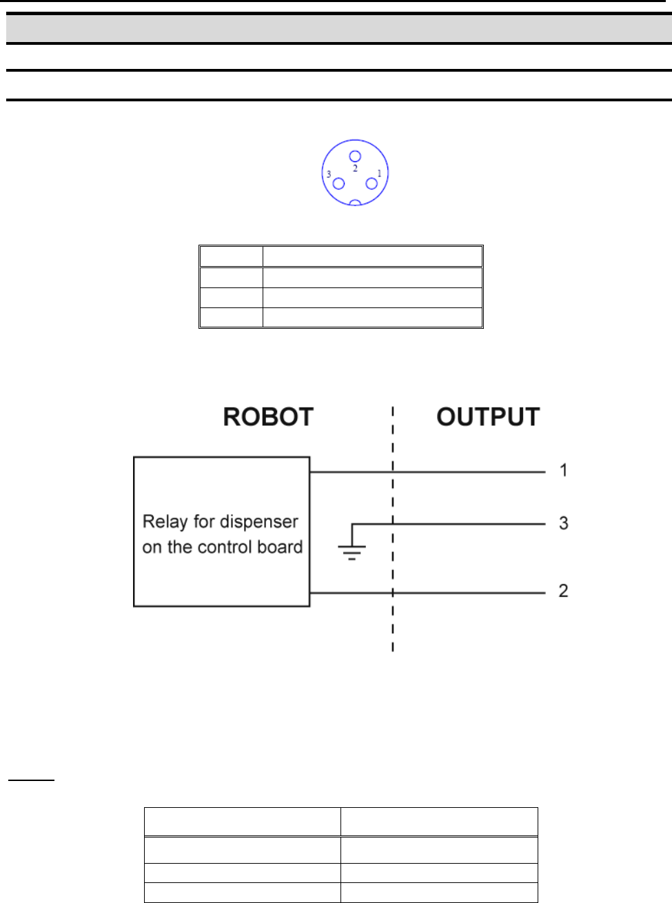
2.1 Dispenser Connector:
Pin #
Description
1
NOM (Normally Open)
2
COM (Common)
3
EARTH (Ground)
Notes:
Maximum Voltage
Maximum Current
125 VAC
12A
250 VAC
7A
30 VDC
7A
F4000N Series Operating Manual
Section 7: Error Messages and Specifications
Part # 562187N-1
Rev. D Sep 2012
101
© 2012 Fisnar Inc.
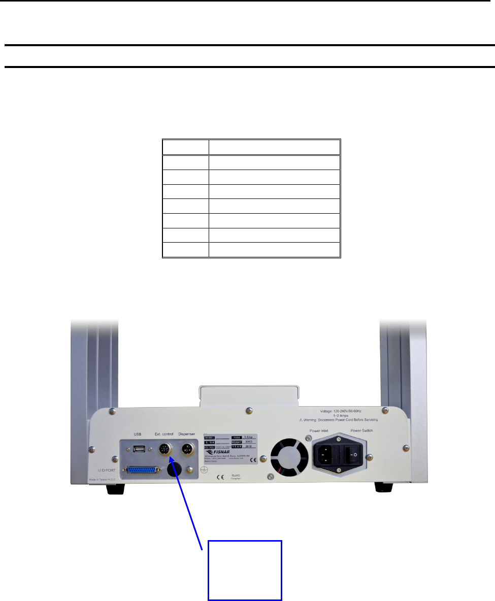
2.2 Ext. Control Connector:
The pin assignments for the external control connector are as follows:
Pin #
Description
1
Start Signal
2
Start Signal
3
Door Switch (COM)
4
Door Switch (NC)
5
Door Switch (NO)
6
Emergency Stop
7
Emergency Stop
External
Control
Connector
F4000N Series Operating Manual
Section 7: Error Messages and Specifications
Part # 562187N-1
Rev. D Sep 2012
102
© 2012 Fisnar Inc.
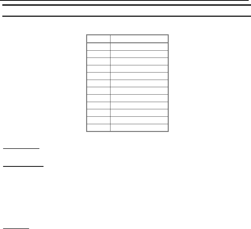
2.3 Output Signals
Pin #
Description
14
OUT #1
15
OUT #2
16
OUT #3
17
OUT #4
18
OUT #5
19
OUT #6
20
OUT #7
21
OUT #8
22
Reserve
23
Reserve
24
+24V
25
+24V
Output Type: Photo-coupler
Output Power:
- F4300/4400/4500N output signals are able to provide a maximum of 24 volts.
- F4300/4400/4500N output signals are able to provide a maximum of 250
milliamps per pin.
Function:
- When the output signal is closed, the circuit between the output pins (#14 - #21)
and the +24 Volt power supply (# 24 & #25) is closed.
- The output pins #14 - #21 are already grounded through the robots internal
power supply.
- Pins #24 & #25 are the same. They are connected to the +24 volt power supply.