F4000N_revD.pdf - 第51页
F4000N Series Operating Manual Section 5: Point T ype & Function Reference Part # 562187N - 1 Rev . D Sep 201 2 50 © 20 12 Fisnar Inc. 1.13 Call Subroutine A subroutine is a set of instructions that are located after…
F4000N Series Operating Manual
Section 5: Point Type & Function Reference
Part # 562187N-1
Rev. D Sep 2012
49
© 2012 Fisnar Inc.
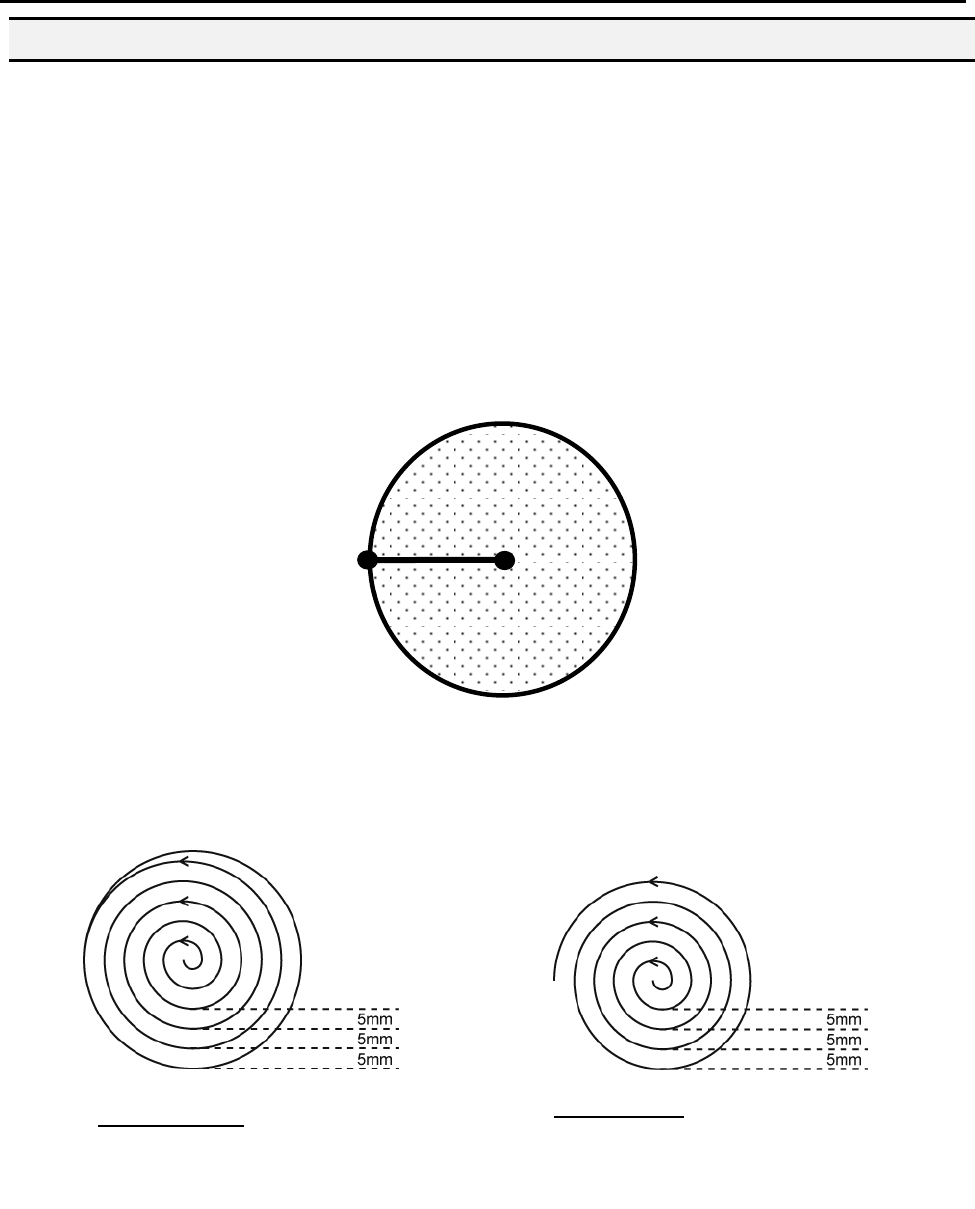
1.12.6 Brush Area: Circle 1
Brush Area: Circle 1, causes the tip to „paint‟ the defined area by following a spiral path
from the center of the circle to the outside limit of the circle. It works in reverse of the
Circle function.
After registering the Brush Area Circle command, jog the tip to a point where you want to
register the center of the circle and register that location as a Line Start. Then jog the tip
directly across on the outside limit of the circle to be brushed and register that location as
a Line End point (the tip will not dispense a straight line between these two points):
If, for example, a brush width of 5 mm was used, the tip will take the following path when
the program is run:
An open or closed option is also available for this function. Selecting the Closed option will
make a whole circle after making the spiral. Selecting the Open option will make the spiral
without closing the outer circle.
Closed Circle1: Creates a spiral from
the center to the outside finishing with
a closed circle.
Line End
Paint
Area
Line
Start
Open Circle1: Creates a spiral from
the center to the outside.
F4000N Series Operating Manual
Section 5: Point Type & Function Reference
Part # 562187N-1
Rev. D Sep 2012
50
© 2012 Fisnar Inc.
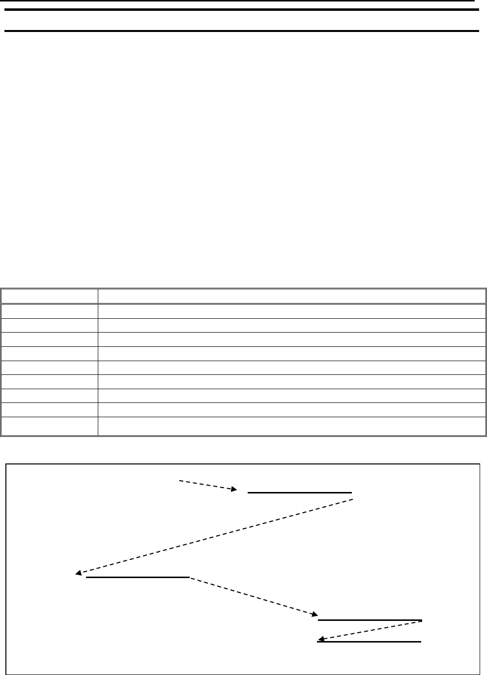
1.13 Call Subroutine
A subroutine is a set of instructions that are located after the End Program instruction.
Call Subroutine causes the machine to jump to a specified memory address and execute
the instructions found there using coordinates specified at the Call Subroutine instruction.
When the End Program instruction for the subroutine is reached, program execution will
continue at the address immediately after the Call Subroutine instruction.
The Call Subroutine function is most useful to repeat a pattern anywhere on the work-
piece, as opposed to the Step & Repeat function where the pattern must be repeated in
straight lines, at fixed distances from each other.
The following example illustrates the use of the Call Subroutine instruction. An
explanation follows.
Address
Instruction
1
Line Speed = 20
2
Call Subroutine (X1,Y1,Z1) address 7
3
Call Subroutine (X2,Y2,Z2) address 7
4
Call Subroutine (X3,Y3,Z3) address 7
5
Call Subroutine (X4,Y4,Z4) address 7
6
End Program
7
Line Start (Xs,Ys,Zs)
8
Line End (Xe,Ye,Ze)
9
End Program
START
Addr. 2
X1,Y1,Z1
Addr. 3
X2,Y2,Z2
Addr. 4
X3,Y3,Z3
Addr. 5
X4,Y4,Z4
END
F4000N Series Operating Manual
Section 5: Point Type & Function Reference
Part # 562187N-1
Rev. D Sep 2012
51
© 2012 Fisnar Inc.
Addresses 7 and 8 comprise the subroutine that will be executed whenever it is called
within the main program. The coordinates in the body of the subroutine
(Xs,Ys,Zs,Xe,Ye,Ze) are not important; the critical information is the relative position to
each other. The actual work will be performed on the coordinates in the main body of the
program.
Before using the Call Subroutine instruction, the tip must be jogged to the first point
where the user wants the work to occur. This point must correspond to the relative first
point defined in the subroutine.
1.14 Call Program
Call Program will jump to the specified program number and execute the program data in
the destination program until the End Program command is reached. When the destination
program is executed, the robot will return to the calling program.
1.15 Set I/O
Set I/O registers an instruction, which either sets the value of an output signal or checks
the status of an input signal.
When the Set I/O function is registered, the user is prompted to select 1. Input or 2.
Output.
If 1. Input is selected; the user can enter the input Port (input # 1 – 8), the input Status
(1/0) and the address to GOTO if that input status occurs. The input status is (0) when the
input pin is connected to ground. The input status is (1) if the input pin is disconnected.
If 2.Output is selected, the user can enter the output Port (output # 0 – 8), and whether
the output should be turned ON or OFF.
Please see SECTION 6:Sample Programs for an example of the Set I/O instruction.