F4000N_revD.pdf - 第103页
F4000N Series Operating Manual Section 7: Error M essages and Specifications Part # 562187N - 1 Rev . D Sep 2012 102 © 20 12 Fisnar Inc. 2.3 Output Sign als Pin # Description 14 OUT #1 15 OUT #2 16 OUT #3 17 OUT #4 18 OU…
F4000N Series Operating Manual
Section 7: Error Messages and Specifications
Part # 562187N-1
Rev. D Sep 2012
101
© 2012 Fisnar Inc.
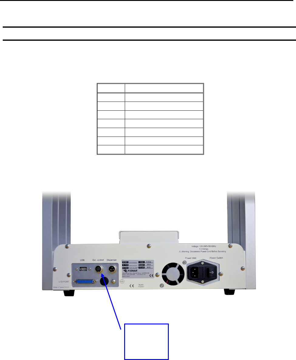
2.2 Ext. Control Connector:
The pin assignments for the external control connector are as follows:
Pin #
Description
1
Start Signal
2
Start Signal
3
Door Switch (COM)
4
Door Switch (NC)
5
Door Switch (NO)
6
Emergency Stop
7
Emergency Stop
External
Control
Connector
F4000N Series Operating Manual
Section 7: Error Messages and Specifications
Part # 562187N-1
Rev. D Sep 2012
102
© 2012 Fisnar Inc.
2.3 Output Signals
Pin #
Description
14
OUT #1
15
OUT #2
16
OUT #3
17
OUT #4
18
OUT #5
19
OUT #6
20
OUT #7
21
OUT #8
22
Reserve
23
Reserve
24
+24V
25
+24V
Output Type: Photo-coupler
Output Power:
- F4300/4400/4500N output signals are able to provide a maximum of 24 volts.
- F4300/4400/4500N output signals are able to provide a maximum of 250
milliamps per pin.
Function:
- When the output signal is closed, the circuit between the output pins (#14 - #21)
and the +24 Volt power supply (# 24 & #25) is closed.
- The output pins #14 - #21 are already grounded through the robots internal
power supply.
- Pins #24 & #25 are the same. They are connected to the +24 volt power supply.
F4000N Series Operating Manual
Section 7: Error Messages and Specifications
Part # 562187N-1
Rev. D Sep 2012
103
© 2012 Fisnar Inc.
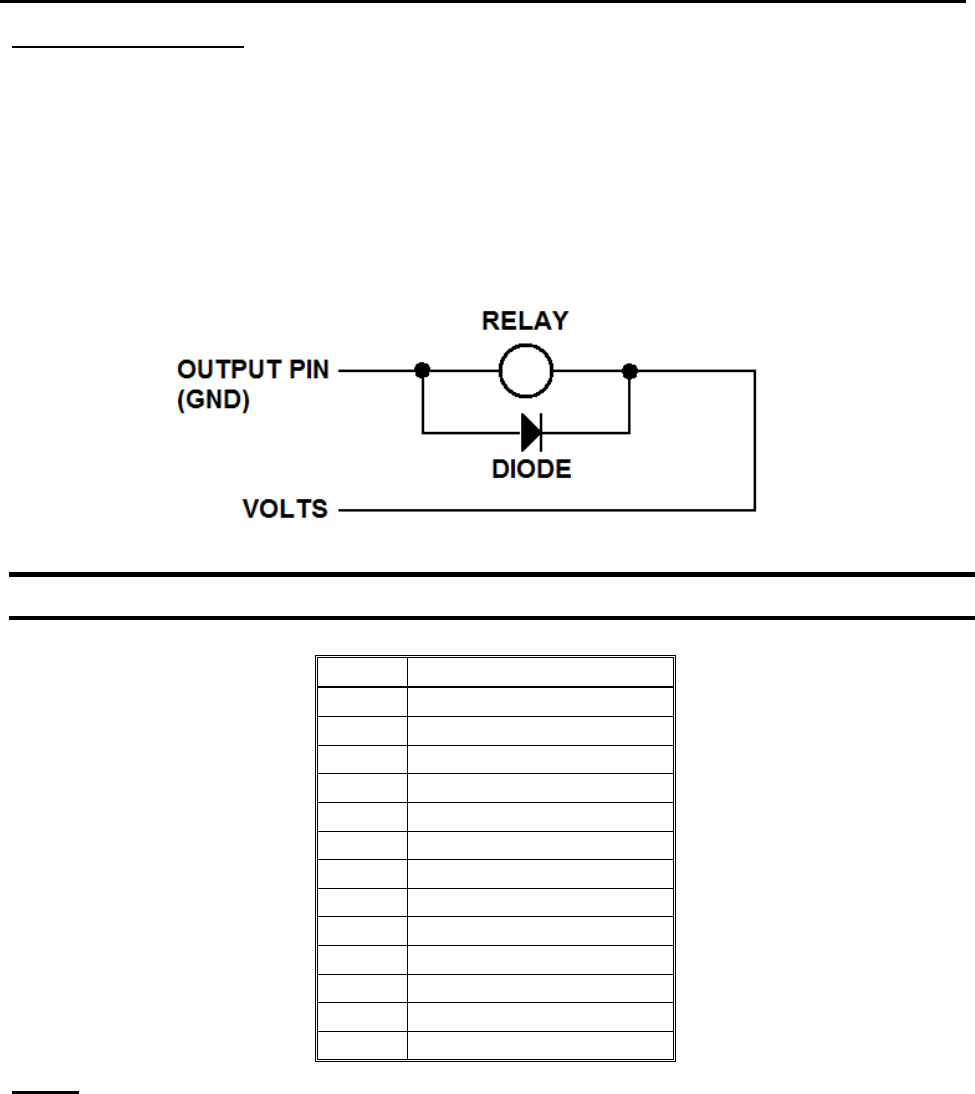
IMPORTANT NOTES:
1. Output signals should be used only to drive external relays. Do not power external
devices directly through output signals. Electrical noise will damage the output
signal relay.
2. If an inductive load (such as a relay) is connected to an output signal, be sure to
install a diode as shown to prevent damage to the output photocoupler:
2.4 Input Signals
Pin #
Description
1
IN # 1
2
IN # 2
3
IN # 3
4
IN # 4
5
IN # 5
6
IN # 6
7
IN # 7
8
IN # 8
9
Reserve
10
Reserve
11
GND
12
GND
13
GND
Notes:
1. To close an input signal, short the circuit between the input pin (1 – 8) and a
GND(ground) pin (pins #11 - 13).
2. Input signals are powered by the robot‟s internal power supply: 24 volts, maximum 2.5
mA
3. Check the status of an input signal using the SET I/O command (see
SECTION 5:1.15 - Set I/O). When the input pin (pin 1 – 8) is connected to a GND pin
(pin #11 - #13), the value of the input is 0.
+24