F4000N_revD.pdf - 第76页
F4000N Series Operating Manual Section 5: Point T ype & Function Reference Part # 562187N - 1 Rev . D Sep 201 2 75 © 20 12 Fisnar Inc. The value wil l be used for all lines from the current memory ad dress forward un…

F4000N Series Operating Manual
Section 5: Point Type & Function Reference
Part # 562187N-1
Rev. D Sep 2012
74
© 2012 Fisnar Inc.
5. F4 (Setup Menu)
Below is a list of functions, which are found under the F4 (Setup) key. These functions are
all related to the setup of dispensing parameters.
5.1 Line Speed
Registers the line speed used for all lines from the current memory address forward until
another Line Speed instruction is found.
5.2 Line Dispense Setup
When dispensing high viscosity materials, there is often a delay from the moment the
dispenser is turned on until the material begins to flow. The following parameters are set
under this function: Head Time, Tail Time, Node Time and Tail Length.
The Head Time setting is a delay time used at the start of line dispensing to prevent the
tip from moving along the line path until the material is flowing. The tip will move to the
start of the line, turn on the dispenser and wait for the time period specified in the head
time setting before moving. The time value can be adjusted to ensure that the material
begins flowing at the same time as the line movement begins.
At the end of dispensing, a delay is often required after the dispenser is turned off, to allow
the barrel pressure to equalize, before moving to the next point location. This prevents
material from being „spilled‟ where it is not wanted. This time delay at the end of
dispensing is called the Tail Time.
The Node Time parameter enters a wait time that only affects the Line Passing
command. Tip will pass through line passing point and will wait at line passing point with
the dispenser activated for the time specified in the Node Time.
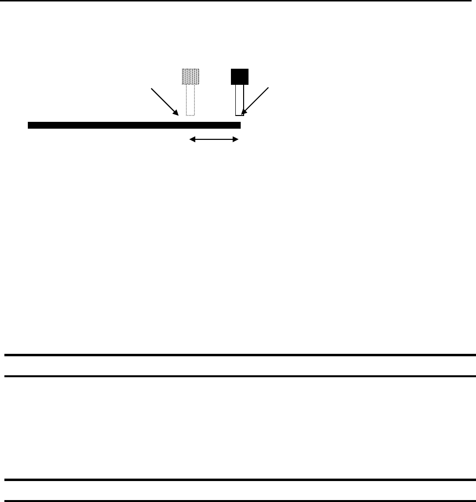
Usually the material continues flowing after the dispenser is off, due to pressure built in
the system. Tail Length automatically turns off the dispenser at a user defined distance
before the end of a line, preventing excess of material to be deposited at the end of the
line.
F4000N Series Operating Manual
Section 5: Point Type & Function Reference
Part # 562187N-1
Rev. D Sep 2012
75
© 2012 Fisnar Inc.
The value will be used for all lines from the current memory address forward until another
Tail Length instruction is found.
Values for the Head Time and Tail Time used when performing line dispensing are
registered by pressing the F4 (Setup) key, then selecting Line Dispense Setup. The set
values will be used by all lines from that memory address forward until new set of Line
Dispense Setup values are found.
Please see SECTION 6:Sample Programs for an example of the Line Dispense Setup
instruction.
5.3 Point Dispense Setup
Registers POINT DISPENSE SETUP values which set dispensing time and waiting time at
the end of dispensing („tail‟ time) for dots. The registered values will be used from the
current memory address forward until another POINT DISPENSE SETUP instruction is
found.
5.4 Dispense End Setup
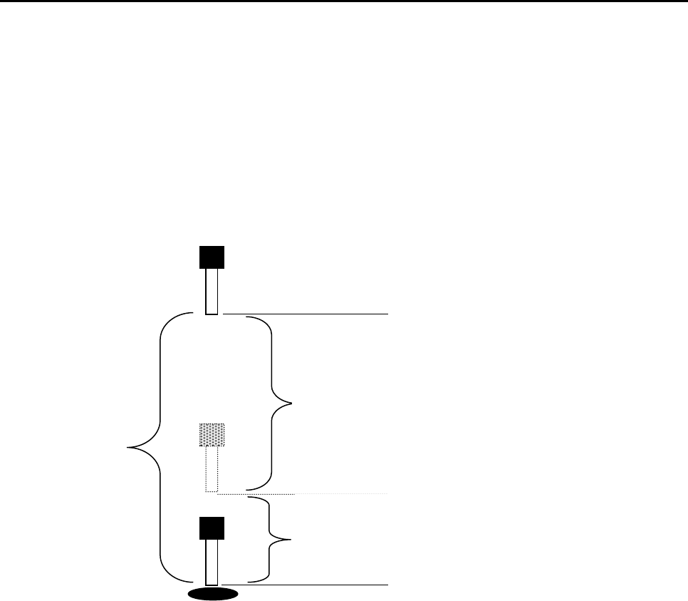
Dispense End Setup allows the L.Length, L. Speed and H. Speed values to be registered
at a memory address. These values will effect how far and how fast the tip rises after
dispensing.
After dispensing a dot or line, it is often required to raise the tip a short distance at a slow
speed. This allows the material to cleanly break free from the tip, without „dragging‟
material where it is not wanted.
Dispenser Turns Off here
Tip continues moving to end of line
Tail Length
F4000N Series Operating Manual
Section 5: Point Type & Function Reference
Part # 562187N-1
Rev. D Sep 2012
76
© 2012 Fisnar Inc.
The distance and speed that the tip raises after dispensing is controlled by the L.Length
and L.Speed settings.
After the tip raises the length specified by L.Length at the speed specified by L.Speed,
the tip will continue rising to the Z Clearance height at the speed specified by H.Speed.
The purpose of specifying a Z Clearance height is to allow the tip to raise high enough to
clear any obstacles it may encounter on the way to the next point.
Values for H.Speed, L.Speed and L. Length are registered with the Dispense End Setup
function by pressing the F4 (Setup) key, then choosing Dispense End Setup.
Once Dispense End Setup values have been registered at a memory address, all points
after that memory address will use the values specified. If Dispense End Setup values are
registered again, at a higher memory address, all points from that memory address
forward will use the new values.
Please see SECTION 6: Sample Programs for an example of the Dispense End Setup
instruction.
H. Speed 2: Tip continues rising to
Z Clearance height at H. Speed
L. Length 1: After dispensing, the tip
rises to L .Length at L. Speed
Z Clearance