fx3r.pdf - 第11页
FX-3R Maintenance Guide 1-3 Rev. 1.00 1-1-2. Y-Axis Magn escale Affixing Position (1) Affix the magnescale while aligning the center portion with the top surface of the Y-frame C and its side surface with the rail side s…
FX-3R Maintenance Guide
1-2
Rev. 1.00
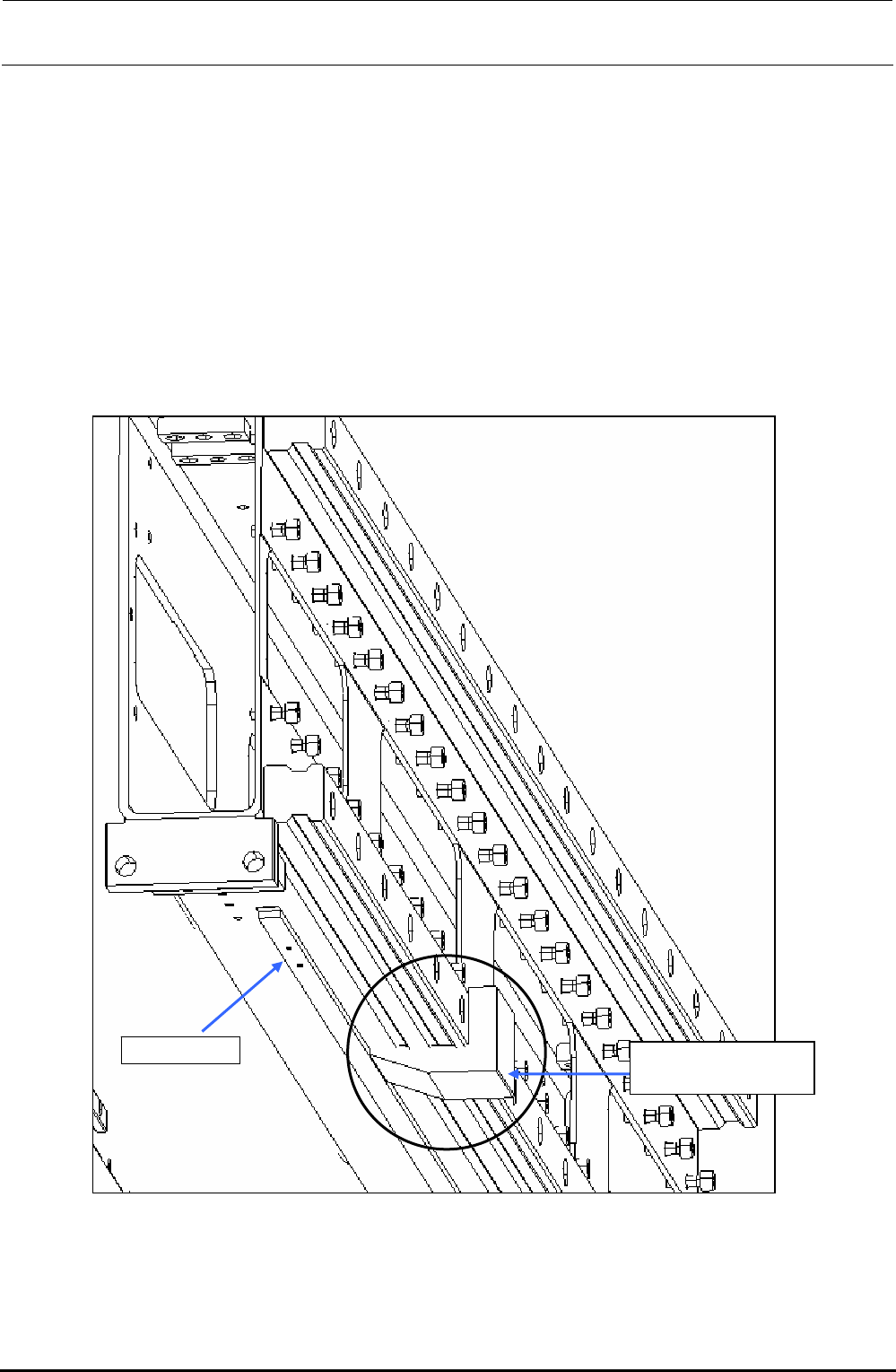
1-1-1. X-Axis Magnescale Affixing Position
(1) Affix the magnescale while guiding it using the X_MSC install jig.
The affixing starting line for the LF/RF is indicated by the mark-off line on the left side when
viewed from the front and that for the LR/RR is indicated by the mark-off line on the left when
viewed from the rear.
Adjust the position of the Z-phase marking on the magnescale side to the mark-off line, and
then affix the magnescale.
Specification value: Magnescale affixing position (Displacement in the direction parallel with the
head movement) ± 0.1mm
Figure 1-1-1-1 Mounting Example of X_MSC Install Jig
40069368
X_MSC install jig
Magnescale
FX-3R Maintenance Guide
1-3
Rev. 1.00
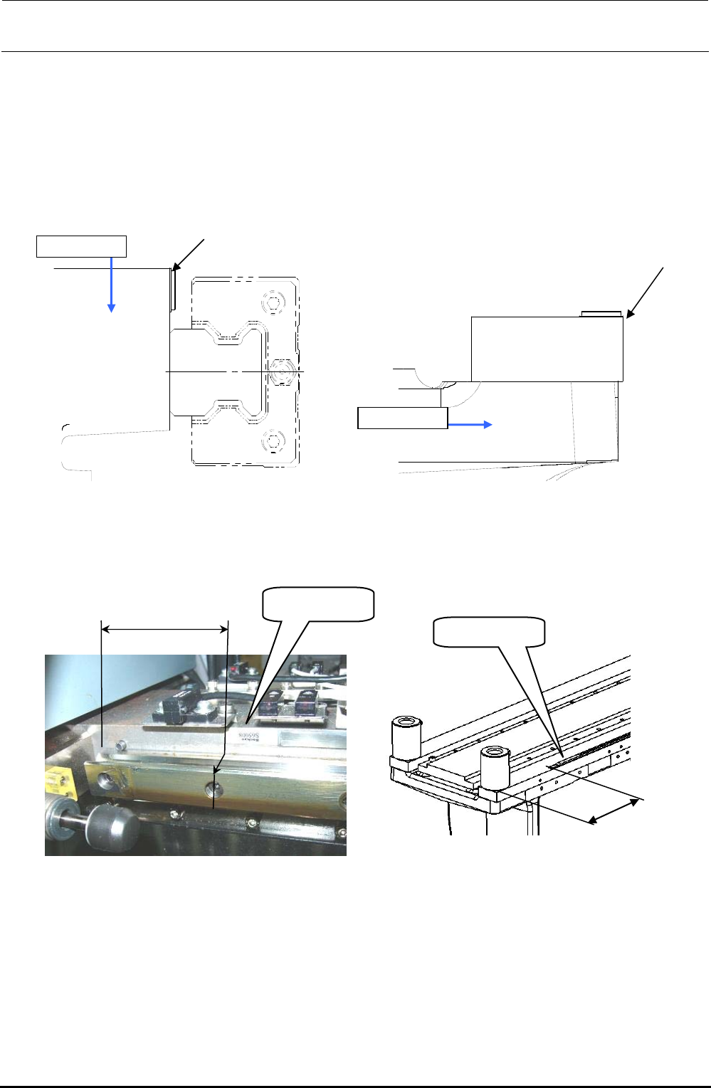
1-1-2. Y-Axis Magnescale Affixing Position
(1) Affix the magnescale while aligning the center portion with the top surface of the Y-frame C and
its side surface with the rail side surface of the Y-frame S.
Specification value: Magnescale affixing position (Displacement in the direction parallel with the
head movement) ± 0.1mm
Figure 1-1-2-1 Y-Axis Magnescale Affixing Position
(Left Figure shown above: Y-frame C, Right Figure shown above: Y-frame S)
Y-frame C
Y-frame S
Alignment with
this surface
Alignment with
this surface
Label side
72±1mm
Figure 1-1-2-2 Y-frame C Affixing Position
Figure 1-1-2-3 Y-frame S Affixing Position
115±1mm
Label side
FX-3R Maintenance Guide
1-4
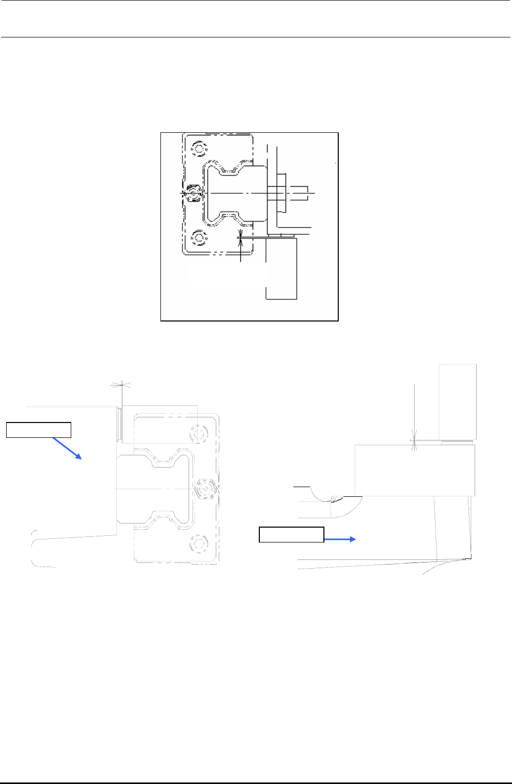
1-1-3. Clearance of the Magnescale
(1) Loosen the screws fixing the sensor and put the clearance jig with a thickness of 0.25 mm in
the clearance between the magnescale and sensor head.
(2) Tighten the set screws of the sensor head to remove the clearance jig with a thickness of
0.25±0.1 mm.
0.25±0.1mm
Figure 1-1-3-1 X-Axis Side
0.25 ± 0.1 mm
0.25 ± 0.1 mm
Y-frame C
Y-frame S
Figure 1-1-3-2 Y-Axis Side
1-1-4. Re-obtaining the Parameters after Replacement of the Magnescale
Follow the work steps stated in section 2.3, Y Setup of the MS parameters to obtain the offset
amount of the right origin position to the left origin position.
Make the correction so that the machine status becomes the factory-settings.
∗ “Y Setup” operation is performed based on the preconditions that the mechanical squareness
has been adjusted completely.
If the mechanical squareness deviates, it is necessary to adjust the mechanical squareness.
(See “X/Y Unit” in the QA Table.)
Rev. 1.00