fx3r.pdf - 第28页
FX-3R Maintenance Guide 2-10 2-3. Replacing the Laser Sensor (LNC60) After the LNC60 has been replaced, it is absolutely necessa ry to re-input the MS parameters related to the laser. (See section 2-7.) 1) Disconnect the…
FX-3R Maintenance Guide
2-9
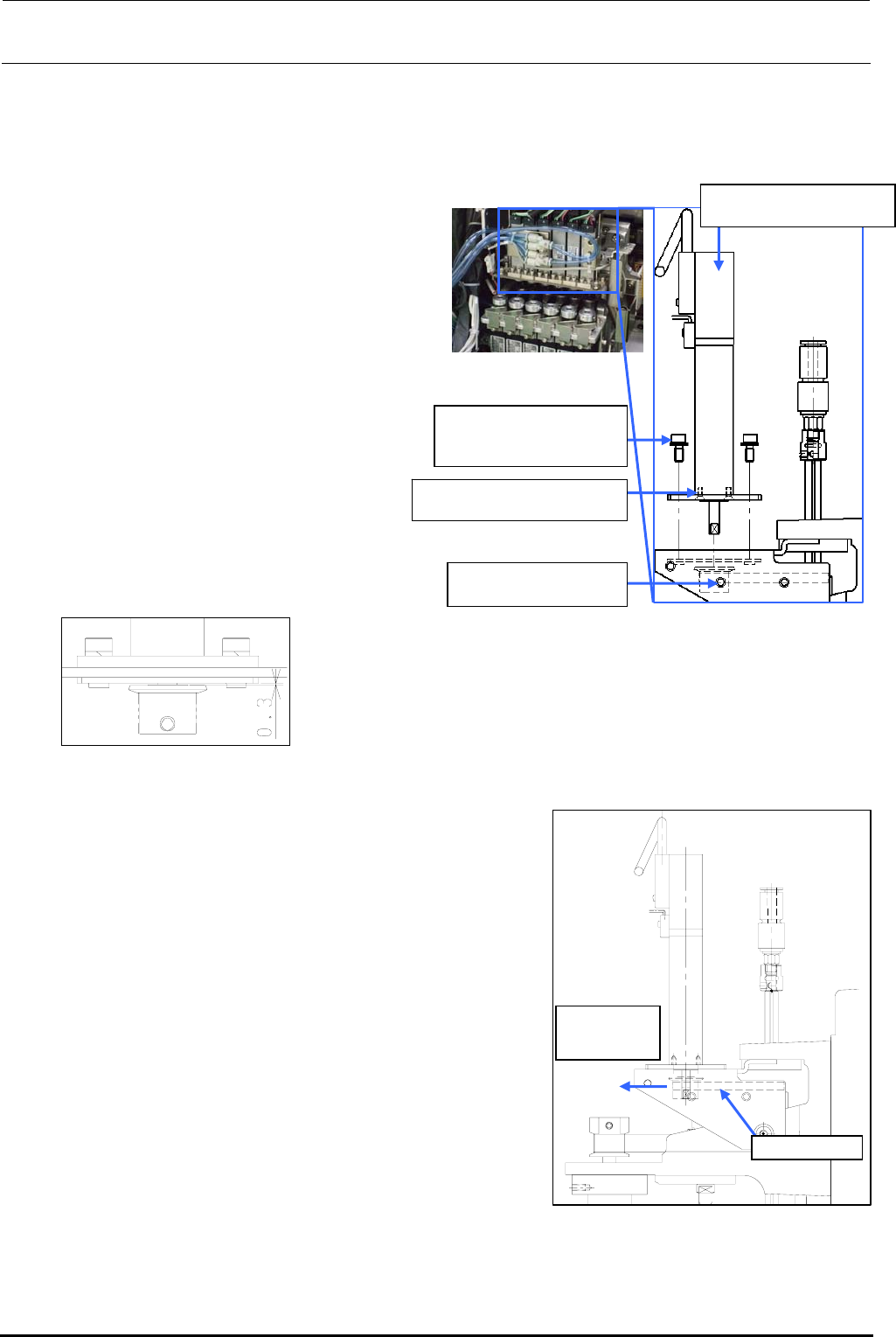
2-2-2. Replacing the θ-Motor
After the θ-motor has been replaced, it is absolutely necessary to re-input the MS parameters
related to the axis home. (For details of input items, see section 2-7.)
1) Disconnect the motor cables from the
servo amplifier board.
(See also steps 2), 3), 8), 9), and 10)
stated in section 2-1.)
Rev. 1.00
2) Loosen the set screws c (hollow set
screws (×1)) of the T pulley.
3) Remove the motor mounting screws d
(SEMS cap bolts (×4)) and pull out the
pulley to detach it.
4) Remove the flat head screws e (×2)
and detach the TM flange.
5) Reassemble the components in the
reverse order of disassembly.
∗ Apply Loctite 242 to the flat head
screws e and tighten them with a
tightening torque of 0.14 N・m.
c SM8030312TP
Set screw M3 L=3
40044533
Servomotor 10W (θ-axis)
SM1020501SC
Flat head screws M2 L=5
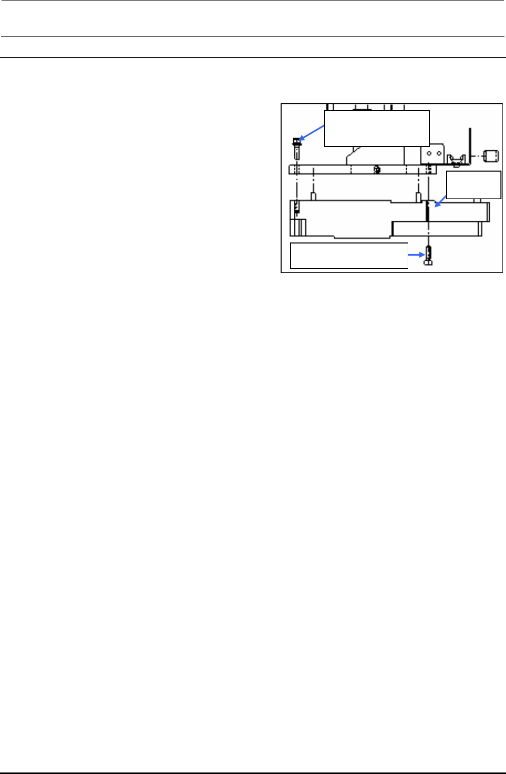
6) Follow the steps below to adjust the belt
tension.
<Belt tension adjustment procedure>
c Make a ring using a tie-up band or belt at the top end
of the T pulley of the θ-motor. Hang the bar tension on
this ring. With the bar tension kept pulled with a force
of 12.7N (1.3kgf), secure the T pulley using the
mounting screws.
Tension meter set value (For check)
• Tension meter input value
Weight: 0.9g/m Width: 4.0mm Span: 38.2mm
• Specification value: 6.5±1N
∗ Apply Loctite 242 to the θ-motor mounting screws (2
pcs.) and tighten them with a tightening torque of 2.3
N・m.
∗ When tightening the setscrew of the T pulley, make
sure to align the orientation of the flat part of the
θ-motor shaft and the setscrew of the pulley. Tighten
the setscrew with a torque of 0.5 N・m.
Timing belt T
Pull by the
force of 12.7N
(1.3kgf)
Figure 2-2-2-2 Adjustment of
the θ-motor Belt
Tension
Assemble so that the clearance
between the T pulley and TM nut
plate is 0.3 mm.
d SL6030842TN
SEMS cap bolt with
washer M3×8
Figure 2-2-2-1 θ-motor
e
FX-3R Maintenance Guide
2-10
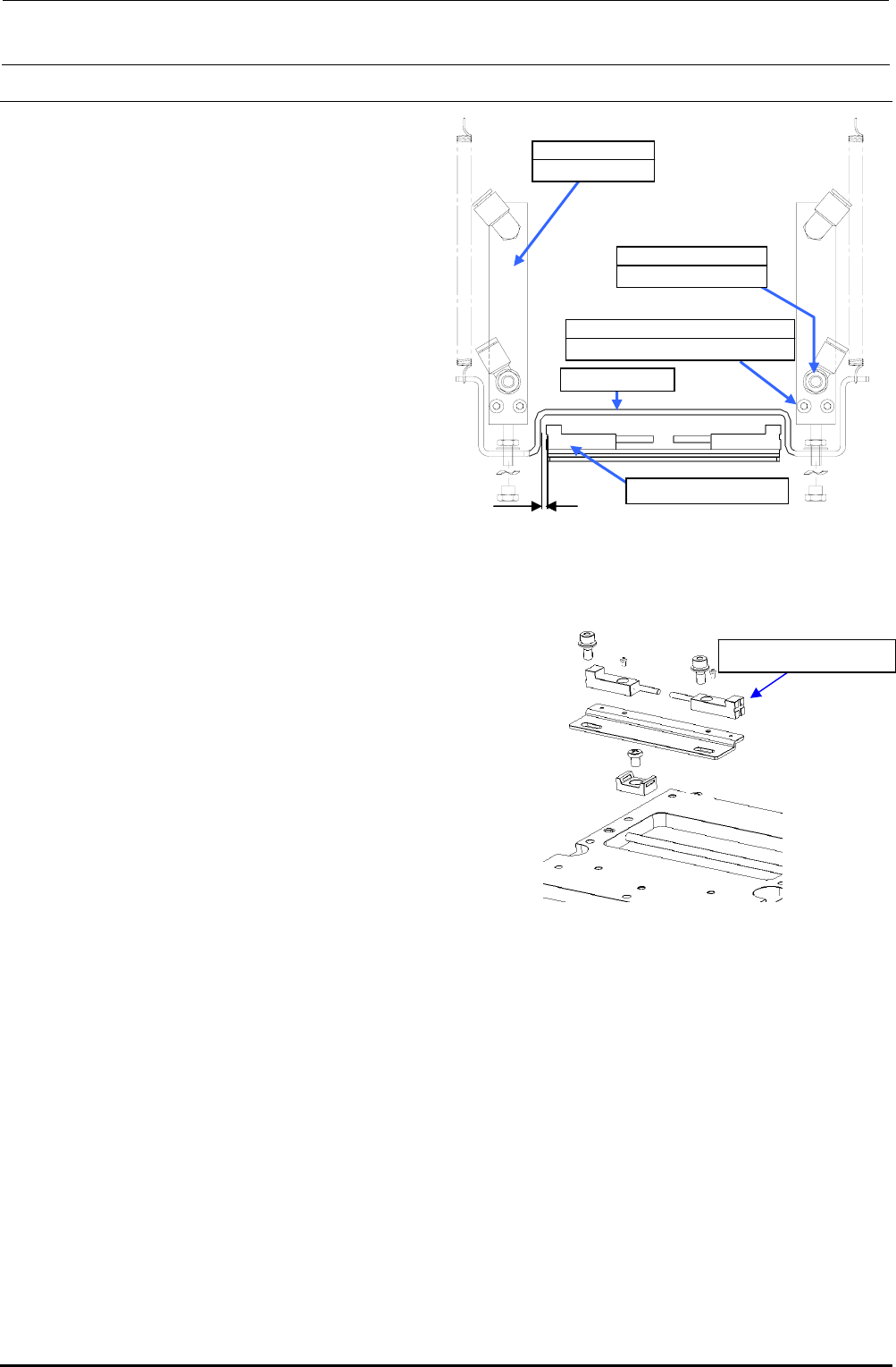
2-3. Replacing the Laser Sensor (LNC60)
After the LNC60 has been replaced, it is absolutely necessary to re-input the MS parameters related
to the laser. (See section 2-7.)
1) Disconnect the connectors (encoder and
IEEE1394) and remove the mounting screws
c and d (3 pcs.) to detach the LNC60.
Rev. 1.00
2) Reassemble the components in the reverse
order of disassembly.
∗ Before mounting the components, remove
Loctite sticking to the sensor bracket as much as
possible.
∗ When attaching the sensor, insert the sensor pin
into the positioning hole of the bracket first. Then
fix the sensor.
∗ Apply Loctite 242 to the sensor mounting screws
c and d and tighten them with a tightening
torque of 2.6 N・m.
∗ After the LNC60 has been replaced, clean the
laser beam window of the LNC60 with a clean
cloth rag.
c SL6041692TN
SEMS cap bolt with
washer M4×16
d SM6041402TN
SEMS cap bolt M4×14
40045547
LNC60
Figure 2-3-1 Laser Sensor
Assembling Position
FX-3R Maintenance Guide
2-11
2-4. Replacing the Head Up Cylinder
Rev. 1.00
1) Turn the finger valve to stop the air supply
and disconnect the air tubes.
2) Remove the head up springs from both
ends, and then remove the nut from the
top end of the air cylinder to detach the
release bar. (Pay special attention so that
the wave washer is not lost.)
3) Remove the cap bolts c (×2) securing the
air cylinder to detach the air cylinder.
(When replacing only the nozzle down
sensor, it is not necessary to detach the
air cylinder.)
4) Remove the cap bolts (×2) securing the
nozzle down sensor bracket to detach the
nozzle down sensor together with the
bracket.
(If the nozzle down sensor needs to be
replaced:)
5) When mounting the air cylinder, adjust the
end face so that it is in parallel to the
cylinder mount and secure them.
Figure 2-4-1 Head-up Cylinder Adjustment
Position
2mm
Nozzle down sensor
c SM6033002TN
SEMS cap bolt M3×30
40046524
Air cylinder
Release bar
PC0105080000
Speed controller
Nozzle down sensor
Figure 2-4-2 Mounting of Nozzle
Down Sensor
6) Mount the nozzle down sensor.
Adjust the nozzle down sensor bracket
position so that the clearance between
the sensor and release bar is 2 mm.
7) If the speed controller has also been
replaced, it is necessary to carry out the
adjustment before mounting the release
bar.
<Speed controller adjustment procedure>
c Call up the MS parameters from the top menu and select [Simple Control] → [MSP] tab in
the function bar. In this status, press the emergency stop button.
d Select [nozzle up cylinder] and turn ON or OFF the cylinder to adjust the displayed time
(msec.) to the specification value. Adjust the time by turning the knob of the speed controller.
Specification value: Air cylinder down time…140±5 msec.
(The difference between the left and right is 5 msec. or less.)
e After the adjustment has been completed, secure the knob firmly.
(8) Insert the release bar into the rod of the cylinder, put the wave washer, and turn the release bar
until the cylinder nut is stopped.
(At this time, it is not necessary to adjust the speed controller and MS parameter.)
∗ Manually operate the solenoid valve to check that the release bar moves up or down
smoothly.