fx3r.pdf - 第194页
FX-3R Maintenance Guide 13-25 [Replacement procedure] c Before starting the replacement work, always turn OFF the main power, main circuit breaker, and main switch. d The SUPERIMPOSE board is located on the right of the …
FX-3R Maintenance Guide
13-24
13-4-8. SUPERIMPOSE Board (40048082)
[Functions]
This SUPERIMPOSE board controls up to two superimpose screens from the CPU board
through the RS-232C. Additionally, this board also captures the touch panel signals through the
RS-232C.
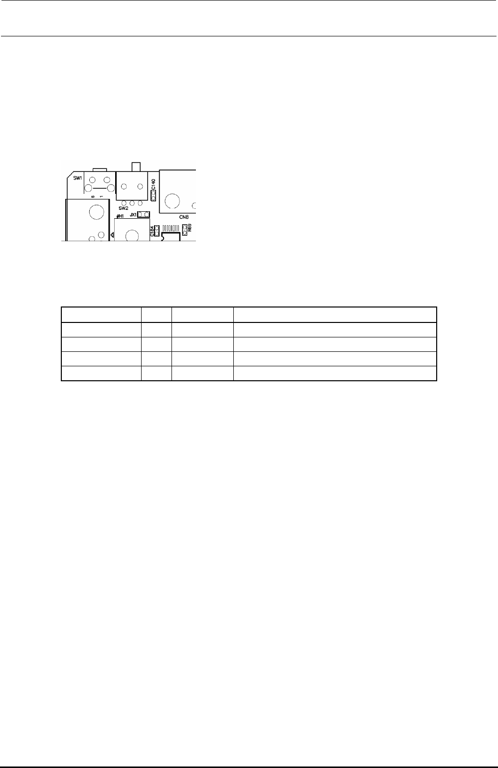
[DIP switch settings]
Always set the slide switch (SW2) as follows.
Figure 13-4-8-1 Slide Switch (SW2)
[Meaning of LED]
There are four LEDs on the board. The following shows the meanings of the indications.
Location No. Color Silk print Indication contents
LD1 Green 12V Lit when 12V is input.
LD3 Red 3.3V Lit when the voltage (3.3V) within the board is correct.
LD4 Red CPU Flashes when the CPU functions correctly.
LD2 Green SYNC Lit when the DVI-D image signal is input.
[Adjustment items after replacement]
There are no particular adjustment items.
Rev. 1.00
FX-3R Maintenance Guide
13-25
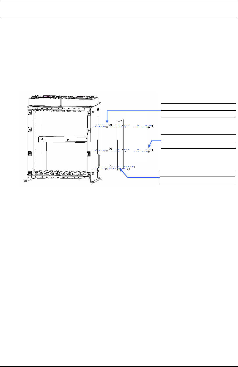
[Replacement procedure]
c Before starting the replacement work, always turn OFF the main power, main circuit
breaker, and main switch.
d The SUPERIMPOSE board is located on the right of the control box. Therefore, take out
the control box and replace the SUPERIMPOSE board.
e After the control box has been taken out, remove SL4030691SC (6 pcs.) to detach the
SUPERIMPOSE board.
f Replace the detached SUPERIMPOSE board with a new one and reassemble the parts
and components in the reverse order of disassembly.
HX00354000N ×6
Spacer
40048082
SUPERIMPOSE BOARD
SL4030691SC ×6
SEMS cap bolt M3×6
Figure 13-4-8-2 Control Unit
Rev. 1.00
FX-3R Maintenance Guide
13-26
13-4-9. ATX Power Supply (40048006)
WARNING
To avoid serious personal injury caused by electric shock, always
turn OFF the main switch completely.
Make sure that the main circuit breaker and main switch of the
main unit are turned OFF.
The main switch is a power switch mounted inside the building and
does not mean a switch on the machine main unit.
[Functions]
This ATX power supply unit supplies DC+3.3V,
DC+5V, DC+12V, DC-12V, and DC+5VSB to the
control box.
If a power failure occurs, the board is backed up
by the connected battery unit (40048007).
[DIP switch settings]
There are no DIP switches on the ATX power
supply.
[Meaning of LED]
There are no LEDs on the ATX power supply.
[Adjustment items after replacement]
Figure 13-4-9-1 ATX Power Supply
There are no particular adjustment items.
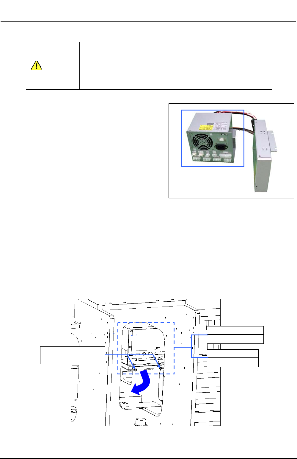
[Replacement procedure]
c Before starting the replacement work, always turn OFF the main power, main circuit
breaker, and main switch.
d Detach the control box.
e Since the ATX power supply is located on the right front side in front of the center of the
base frame. Disconnect the cables, such as AC input cable and RS232C cable from the
ATX power supply.
f Remove SL4040891SC (2 pcs.) from the front. Raise the ATX power supply together
with the ATX bracket (40063463). This allows you to detach the ATX power supply
toward you.
40048006
ATX power supply
40063463
ATX bracket
SL4040891SC ×2
SEMS cap bolt M4×8
Figure 13-4-9-2 ATX Power Supply Position
Rev. 1.00