fx3r.pdf - 第8页
FX-3R Maintenance Guide vi Rev. 1.00 15-3. Replacing the Movable Cutter Blade (Bo ttom Blade) of the Tape Cutter ............ 15-10 15-4. Replacing the Fixed Cutter Blade (Upper Blade) of the T ape Cutter ...............…

FX-3R Maintenance Guide
v
Rev. 1.00
13-4-2. CPU Board (40107372) ................................................................................................... 13-17
13-4-3. Position Board (40044540) .............................................................................................. 13-18
13-4-4. cPCI-8994 Board (40048003) .......................................................................................... 13-19
13-4-5. ETHER-MAIN Board (40048066)..................................................................................... 13-20
13-4-6. IP-X5 Board Assembly (40047528).................................................................................. 13-21
13-4-7. MOUSE/KEYBOARD Selector (40003281)...................................................................... 13-22
13-4-8. SUPERIMPOSE Board (40048082)................................................................................. 13-24
13-4-9. ATX Power Supply (40048006)........................................................................................ 13-26
13-4-10. Battery Unit (40048007)................................................................................................... 13-28
13-5. X-Y Unit ..............................................................................................................13-30
13-5-1. Structure of X-Y Unit ........................................................................................................ 13-30
13-5-2. Display Indication of XY Servo Amplifier.......................................................................... 13-31
13-6. Z-θ Unit...............................................................................................................13-32
13-6-1. Structure of Z-θ Unit......................................................................................................... 13-32
13-6-2. LED Indications................................................................................................................ 13-33
13-7. Transport Unit.....................................................................................................13-34
13-7-1. Structure of Transport Unit............................................................................................... 13-34
13-7-2. Adjusting the BASE-CARRY Board (40047559) .............................................................. 13-44
13-7-3. Adjusting the Stepping Driver........................................................................................... 13-44
13-8. Head Unit............................................................................................................13-47
13-8-1. Adjusting the Boards of the Head Unit ............................................................................. 13-47
13-9. Covers ................................................................................................................13-49
13-9-1. Structure of Operation Unit .............................................................................................. 13-49
13-9-2. Jumper Switch Settings on the Operation Board Assembly............................................. 13-49
13-9-3. Mounting Switches onto the Operation Switchboard........................................................ 13-51
13-10. Replacing the Fuse of the AC Input Unit ............................................................13-58
13-11. Other Boards ......................................................................................................13-59
13-11-1. XY-RELAY Board (40047558) ......................................................................................... 13-59
13-11-2. FEEDER Board (40047560)............................................................................................. 13-61
13-12. Adjusting the Dial of the Vacuum Pump Electromagnetic Switch
(Thermal Protector) ............................................................................................13-62
[14] FEEDER POSITION INDICATOR (FPI)................................................14-1
14-1. Detaching the FPI (Front) from the Machine Main Unit ........................................14-1
[15] TAPE CUTTER (OPTIONAL)................................................................15-1
15-1. Overall Drawing ....................................................................................................15-1
15-1-1. Tape Cutter for Electric Fixed Bank Specification .............................................................. 15-2
15-2. Replacing the Tape Cutter Main Unit....................................................................15-3
15-2-1. Assembling and Adjusting the Lower Discharge Guide ..................................................... 15-8

FX-3R Maintenance Guide
vi
Rev. 1.00
15-3. Replacing the Movable Cutter Blade (Bottom Blade) of the Tape Cutter............15-10
15-4. Replacing the Fixed Cutter Blade (Upper Blade) of the Tape Cutter ..................15-12
15-5. Grease up...........................................................................................................15-13
[16] FX-3R JIG LISTS ..................................................................................16-1
FX-3R Maintenance Guide
1-1
DANGER
To prevent any trouble caused by accidental machine start, always
shut-down the power before starting the maintenance and
adjustment work.
The XY-axis uses a very strong magnet.
• Do not put any metallic object close to the magnet surface. Once the
magnet attracts a metallic object, this object cannot be removed due to
strong magnetic force.
• Before starting the maintenance work, take off precision portable devices,
such as a wrist watch from your body.
• Do not allow personnel who uses a precision medical device, such as an
artificial cardiac pacemaker, etc to carry out the maintenance work.
[1] X-Y UNIT
1-1. Replacing the Magnescale
(1) Detach the magnescale head from the bracket.
(2) Peel off the old magnescale.
(3) Degrease the magnescale mounting surface and magnescale completely.
Note 1: Before replacing the magnescale, put the magnescale near the machine and leave
it for 1 hr. or longer to make the temperature of the magnescale similar to that of the
machine.
Note 2: “Mecha fine mate” is recommended for the degreasing agent.
Note 3: Deviation amount when compared to the specified value of the magnescale in the
X-direction:
±
0.1 mm or less.
Note 4: Do not put any magnet, such as magnetized screwdriver or support pin close to the
magnescale. Doing so may cause the magnescale to malfunction.
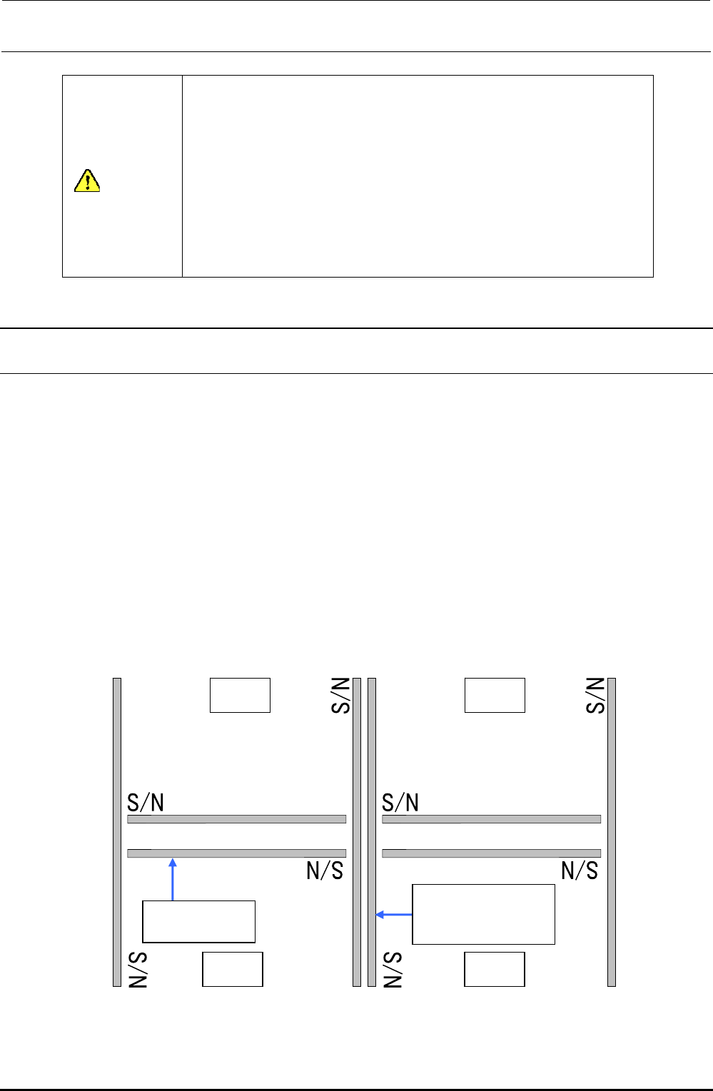
Note 5: The magnescale has a correct orientation. Affix it in the direction shown in the figure
below.
LR RR
LF RF
40091396
40048080(For XL)
Magnescale Y
40048026
Magnescale X
(∗ S/N: Serial No. of the magnescale)
Figure 1-1-1 Affixing Orientation of the Magnescale (Main Body Top View)
Rev. 1.00