fx3r.pdf - 第201页
FX-3R Maintenance Guide 13-32 13-6. Z- θ Unit The Z- θ unit is composed of an AC servo amplifier that drives the Z/ θ -axes. 13-6-1. Structure of Z- θ Unit In the AC servo amplifier for the Z- θ unit, one driver can driv…
FX-3R Maintenance Guide
13-31
[Adjustment items after replacement]
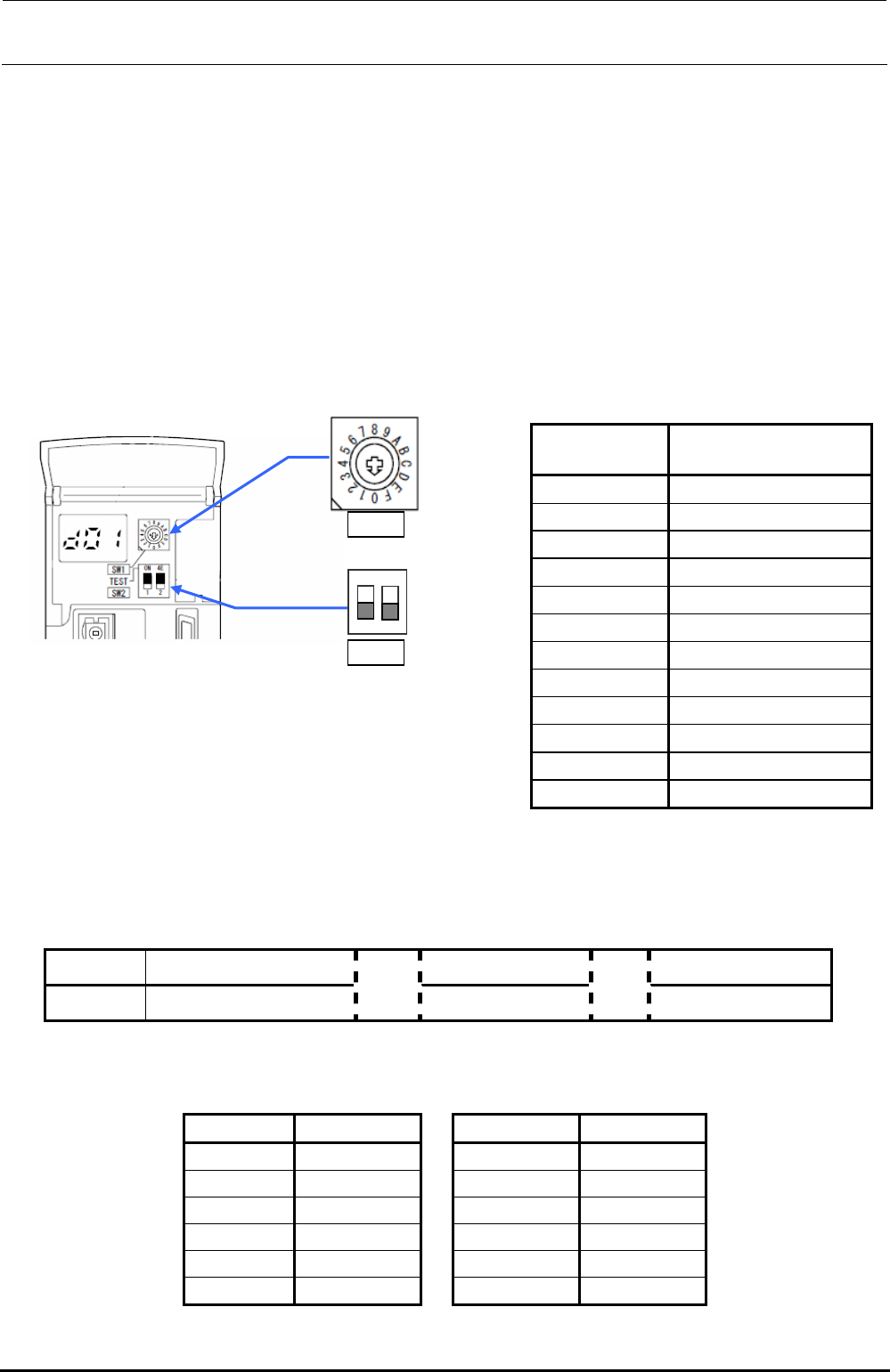
When replacing the servo amplifier, it is necessary to set the axis selection with the rotary switch
(SW1) on the servo amplifier of each axis.
Open the front cover of the servo amplifier and turn the rotary switch (SW1) for the axis selection
so that the arrow mark indicates the following set value.
Make sure that the DIP switch (SW2) is OFF.
After the adjustment has been completed, turn ON the power to the main unit and turn it OFF.
After that, restart the operation.
Note. When the main unit is started up for the first time after the servo amplifier has been
replaced, do not perform the origin return.
Table 13-5-1-1 Rotary Switch Settings
Servo amplifier
Axis selection switch
set values
X (LF) 0
X (LR) 1
YL (LF) 0
YR (LF) 1
YL (LR) 2
YR (LR) 3
X (RF) 0
X (RR) 1
YL (RF) 0
YR (RF) 1
YL (RR) 2
YR (RR) 3
1
2
ON
SW1
SW2
13-5-2. Display Indication of XY Servo Amplifier
A 7-segment LED that indicates the status is mounted on the front of the XY servo amplifier.
Normally, this LED shows the status as described below.
Table 13-5-2-1 7-Segment LED Indication
Indication Ab C# d#
Contents Initialization is in progress.
→
Servo OFF
→
Servo ON
∗ Axis No. is shown in the “#” portion. (See also the Table below.)
Table 13-5-2-2 7-Segment LED Indication
Axis Axis No.
Axis Axis No.
X (LF)-axes 01
X (RF)-axes 01
X (LR)-axes 02
X (RR)-axes 02
YL (LF)-axes 01
YL (RF)-axes 01
YR (LF)-axes 02
YR (RF)-axes 02
YL (LR)-axes 03
YL (RR)-axes 03
YR (LR)-axes 04
YR (RR)-axes 04
Rev. 1.00
FX-3R Maintenance Guide
13-32
13-6. Z-θ Unit
The Z-θ unit is composed of an AC servo amplifier that drives the Z/θ-axes.
13-6-1. Structure of Z-θ Unit
In the AC servo amplifier for the Z-θ unit, one driver can drive 4 axes. Therefore, 3 drivers are
installed in FX-3.
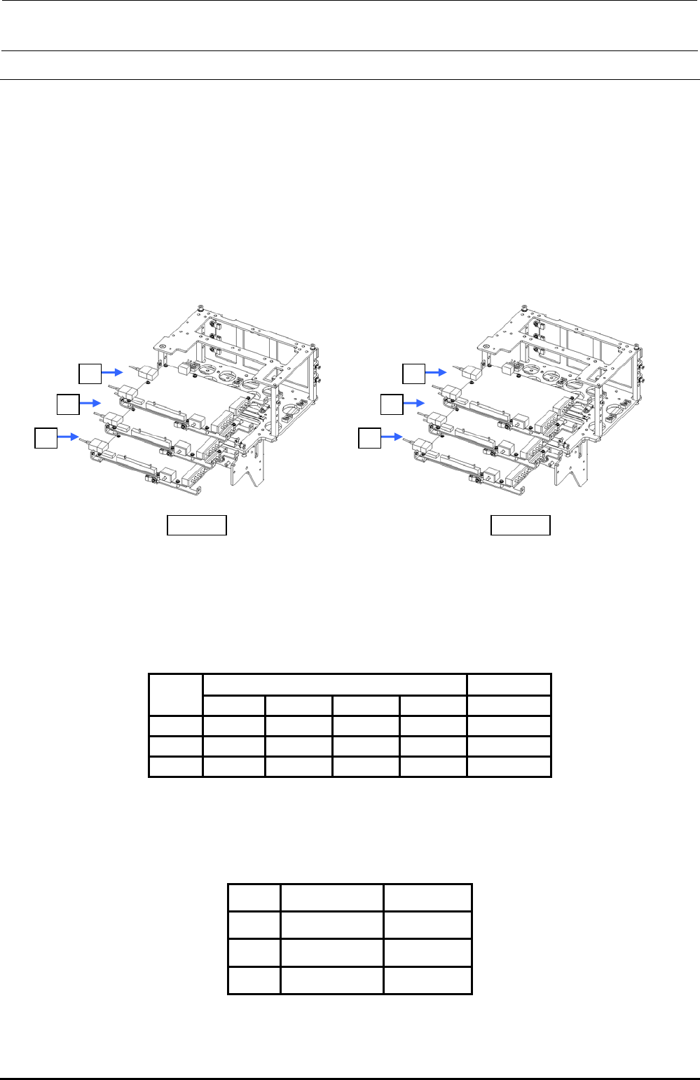
4-axis integrated type servo amplifier board for the Zθ-axis is mounted in the head unit. Actually,
three boards are mounted in the vertical direction.
Figure 13-6-1-1 shows the relationship among each motor and servo amplifier.
LF/RR
c
d
e
LR/RF
e
d
c
Figure 13-6-1-1 Structure of Z/θ Unit
∗ Motor outputs
Z-axis: 30W
θ-axis: 10W
Table 13-6-1-1 Z/θ-Unit Layout Relational Diagram
Axis No. on amplifier
Symbol
Axis No. 1 Axis No. 2
Axis No. 3
Axis No. 4
Part No.
c
L2 θ-axis L2 Z-axis
L1 θ-axis L1 Z-axis
40044535
d
L4 θ-axis L4 Z-axis
L3 θ-axis L3 Z-axis
40044535
e
L6 θ-axis L6 Z-axis
L5 θ-axis L5 Z-axis
40044535
For the Zθ-servo amplifier, set the rotary switch (CS1) appropriately according to the board.
Table 13-6-1-2 Z/θ-Unit Layout Relational Diagram
Symbol
Servo amplifier
SW set value
c
L1, 2 Z/θ-axis
1
d
L3, 4 Z/θ-axis
2
e
L5, 6 Z/θ-axis
3
Rev. 1.00
FX-3R Maintenance Guide
13-33
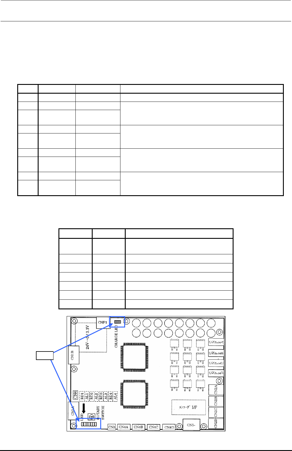
13-6-2. LED Indications
Nine LEDs are mounted on the Zθ-servo amplifier.
These LEDs show the status of each axis as described below. The following shows the
correspondence among each axis and LEDs.
Table 13-6-2-1 Zθ-Driver LEDs
No. LED name Indication color
Operation
1 CHARGE Lights up when any electric charge exists in the main circuit.
2 RD1 Green
3 AL1 Red
Shows the status of axis No. 1 (L2θ-, L4θ-, and L6θ-axis).
For details about the status expressed by the combination of RD1 and
AL1, see the Table below.
4 RD2 Green
5 AL2 Red
Shows the status of axis No. 2 (L2Z-, L4Z-, and L6Z-axis).
For details about the status expressed by the combination of RD2 and
AL2, see the Table below.
6 RD3 Green
7 AL3 Red
Shows the status of axis No. 3 (L1θ-, L3θ-, and L5θ-axis).
For details about the status expressed by the combination of RD3 and
AL3, see the Table below.
8 RD4 Green
9 AL4 Red
Shows the status of axis No. 4 (L1Z-, L3Z-, and L5Z-axis).
For details about the status expressed by the combination of RD4 and
AL4, see the Table below.
The following shows the operation status expressed by the combination of RD∗ and AL∗.
Table 13-6-2-2 Combination of Zθ-Driver LED Lighting and Flashing Statuses
RD∗ AL∗
Status
Flashing Flashing
Controller is not connected (immediately after
the power has been turned ON).
Flashing Off
Servo is OFF.
Lit Off
Servo is ON.
Off Flashing Warning occurs.
Off Lit
Alarm occurs.
Lit Lit
S/W installation status
Off Off
Control power is OFF.
LED
Figure 13-6-2-1 LEDS of the Z/θ amplifier
Rev. 1.00