fx3r.pdf - 第170页
FX-3R Maintenance Guide 13-1 DANGER To prevent any trouble caused by accidental machine start, always shut-down the power before starting the maintenance and adjustment work. [13] ELECTRICAL COMPONENTS 13-1. Layout of El…
FX-3R Maintenance Guide
12-40
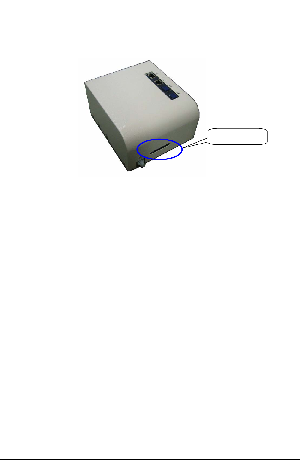
When mounting the cover again, assemble the cable as shown in the Figure so that it does not block
the cover window. Make sure that the LED lamps can be seen through the window.
Cover window
Figure 12-3-3 Cover Window
Rev. 1.00
FX-3R Maintenance Guide
13-1
DANGER
To prevent any trouble caused by accidental machine start, always
shut-down the power before starting the maintenance and
adjustment work.
[13] ELECTRICAL COMPONENTS
13-1. Layout of Electrical Components
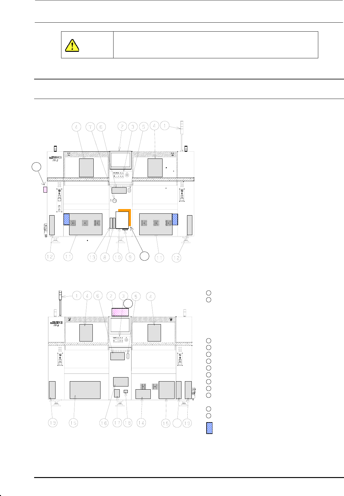
Figure 13-1-1 shows the front view and Figure 13-1-2 shows the rear view.
c Signal tower
d LCD monitor
e Operation panel
Front: Operation board front assembly
Rear: Operation board rear assembly
(EN assembly for machines with EN
specifications)
f Head unit
21
Head main board assembly, Z/θ-servo
amplifier, HMS, OCC camera, OCC light
board
(OCC-A board assembly, OCC-C board
assembly),
Bad mark reader (Optional)
g Mouse
h Keyboard
i Power switch
j FDD
k SSD
l Control unit
Inside: CPU board, POSITION board,
IEEE1394A board, IP-X5 board,
CPCI back board
20
Figure 13-1-1 Front View
Outside: Superimpose board,
Mouse/keyboard change-over
board
11
XY-driver unit
12
Transport unit system electrical
components
5-phase stepping drivers (For transport
motor, auto PWB width adjustment, and
backup table), Base carry board assembly
(One board on right side only.)
22
13
DVD-ROM & CD-R/RW drive
14
Vacuum pump
15
Power supply unit
16
AC input unit L, AC input unit R
17
Circuit breaker
18
Hour meter
19
Feeder board assembly
20
ATX power supply
21
Barcode reader (Optional)
∗ To be installed on the transport IN side.
22
HUB-BOX (Optional)
23
XY-RELAY board assembly
23
portion Tester for CVS
Figure 13-1-2 Rear View
Rev. 1.00
FX-3R Maintenance Guide
13-2
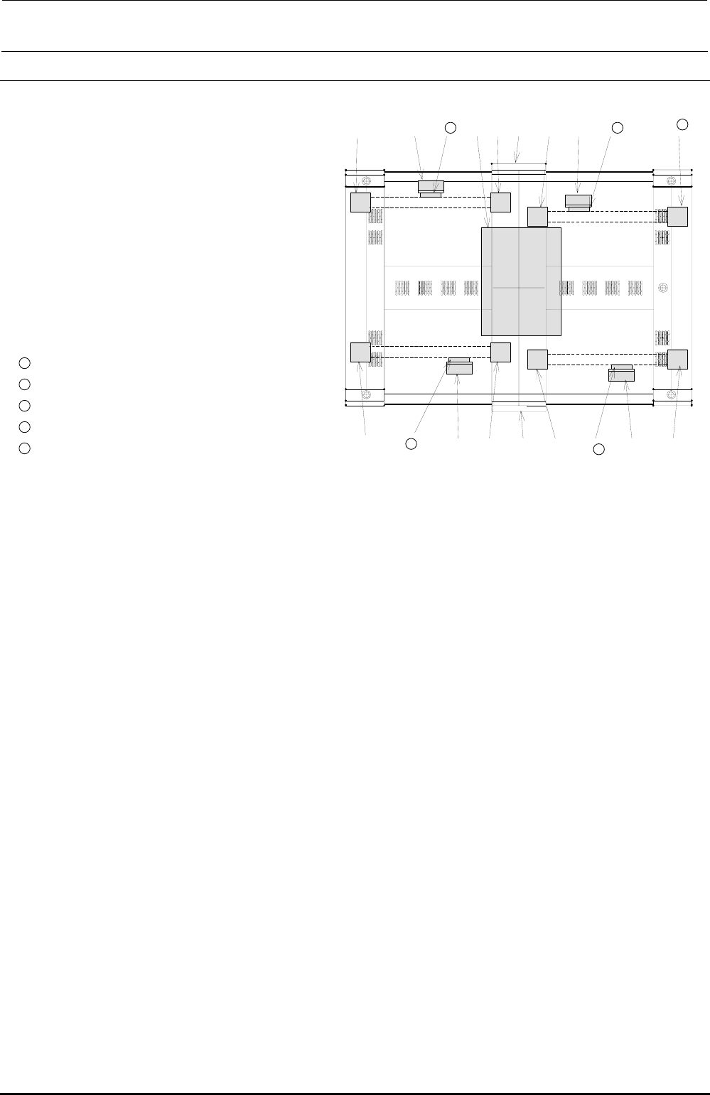
13-2. Layout of Top of Base Frame
Figure 13-2-1 shows the base frame top view.
Rev. 1.00
h
ed 13 i c l d
11
15
c LCD monitor
d Head unit
e Transformer
f YL-LF-axis motor
g YR-LF-axis motor
h YL-LR-axis motor
i YR-LR-axis motor
j YL-RF-axis motor
k YR-RF-axis motor
l YL-RR-axis motor
11
YR-RR-axis motor
12
X-LF-axis motor
13
X-LR-axis motor
14
X-RF-axis motor
f
12
d
g
c
j
15
X-RR-axis motor
14
d
k
Figure 13-2-1 Base Frame Top View