fx3r.pdf - 第135页
FX-3R Maintenance Guide 12-6 12-2-2. Setting Up the BIOS After the SSD has been replaced, check the BIOS. If the settings are different from those described in <Setting Method>, change the set tings appropriately. …
FX-3R Maintenance Guide
12-5
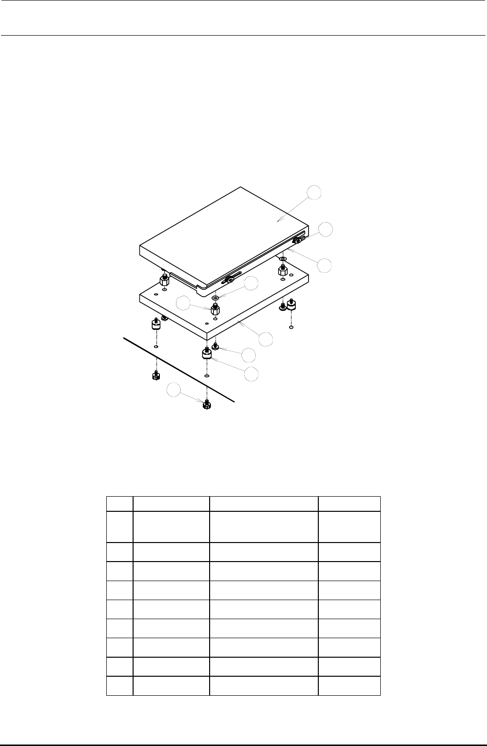
12-2-1-2. Replacing the SSD
The SSD is installed on the control support.
1) Remove the SEMS cap bolts to detach the overall SSD from the bracket while carefully
checking the IDE connector status.
2) Remove the SEMS cap bolts to detach the SSD bracket and disconnect the IDE
connector.
3) Remove the bolts and to detach the SSD from the weight plate .
4) Reassemble the components in the reverse order of disassembly.
Rev. 1.00
1
2
3
4
5
6
7
8
9
Figure 12-2-1-2-1 Replacement of SSD
[List of Replacement Parts]
Table 12-2-1-2-1 SSD Replacement Parts
No. Part No. Part name Q’ty/machine
40109193
ENVIRONMENT
SYSYTEM 132 ASM
1
40057003 SSD bracket 1
SL4030681SC
SEMS cap bolt (M3×6)
2
WP0320501SC Flat washer M3 4
E3032700000 Extension nipple 4
40011588 Weight plate 1
SL4030881SC
SEMS cap bolt (M3×8)
4
E1612721000 Vibration proof rubber 4
SL4030881SC
SEMS cap bolt (M3×8)
4
FX-3R Maintenance Guide
12-6
12-2-2. Setting Up the BIOS
After the SSD has been replaced, check the BIOS. If the settings are different from those described
in <Setting Method>, change the settings appropriately. In addition, if the CPU board is replaced, it
is absolutely necessary to change the BIOS.
Note: BIOS (Basic Input Output System)
The BIOS is an important program necessary to control the data input and output.
Therefore, always carefully operate the BIOS
. Normally, the programs are saved
into the flash memory on the CPU board and the setup data is saved into the SRAM
backed up by the battery.
Caution
12-2-2-1. Checking the Recognition of the SSD
You may check whether or not the BIOS recognizes the SSD correctly. If no automatic startable
SSD or FDD is found after memory check, the following message will appear.
Operating system not found
You can switch to the BIOS setting screen by pressing the <S> key. (Pressing the <R> key will
reset the unit.)
<Setting Method>
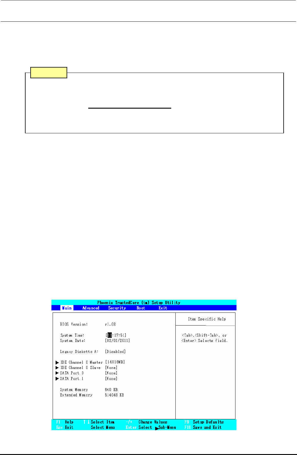
1) Display the BIOS screen.
Press the <F2> key while the “Phoenix Technologies” screen is displayed immediately
after the power has been turned ON.
After the operation step has moved to the BIOS setting, the following screen will appear.
Select a menu screen (Main, Advance, Security, Boot, Exit) with the [←] or [→] key, move
the cursor (highlighted portion) with the [↑] or [↓] key, and then press the <Enter> key to run
the item you have selected.
Figure 12-2-2-1-1 Screen Displayed after Moving to BIOS Setting
Rev. 1.00
FX-3R Maintenance Guide
12-7
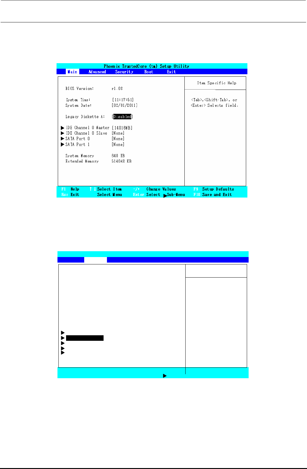
2) Set the floppy disk drive.
Select the “Main” menu screen with the [←] or [→] key. Move the cursor (highlighted
portion) to “Legacy Diskette A:” with the [↑] or [↓] key, and press the <ENTER> key. Select
“Disabled”, and press the <ENTER> key.
Figure 12-2-2-1-2 BIOS Screen (Main Screen)
3) Select the “PnP Configuration” screen.
Select the “Advanced” menu screen with the [←] or [→] key. Move the cursor (highlighted
portion) to “PnP Configuration” with the [↑] or [↓] key, and press the <ENTER> key.
Phoenix TrustedCore (tm) Setup Utility
Main Advanced Security Boot Exit
Item Specific Help
Reset Configuration Data: [No]
Large Disk Access Mode: [DOS]
Local Bus IDE adapter: [Primary] Select
‘
Yes
’
if you
Legacy USB Support: [Enabled] Want to clear the
Summary Screen: [Disabled] Extended System
Boot-time Diagnostic Screen: [Disabled] Configuration
QuickBoot Mode: [Enabled] Data (ESCD) area.
Extended Memory Testing: [Just Zero it]
PXE OPROM: [Disabled]
Keyboard Features
PnP Configuration
CPU Control Sub-Menu
ICH Control Sub-Menu
SIO Control Sub-Menu
F1 Help ↑↓Select Item -/+ Change Values F9 Setup Defaults
Esc Exit Select Menu Enter Select Sub-Menu F10 Save and Exit
Figure 12-2-2-1-3 BIOS Screen (Advanced Screen)
Rev. 1.00