fx3r.pdf - 第215页
FX-3R Maintenance Guide 13-46 <Adjustment Procedure for Machines Applicable to EN> c Set the rotary switches to the values in the table below. Rev . 1.00 Switch Settings STOP (For support table) STOP (For auto widt…
FX-3R Maintenance Guide
13-45
13-7-3-2. Setting the Stepping Motor Driver for Support Table/Auto Width Adjustment
<Adjustment Procedure for Machines not Applicable to EN>
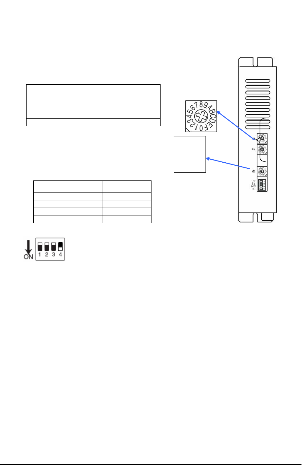
c Set the rotary switches to the values in the table below.
Rev. 1.00
Switch Settings
STOP (For support table)
STOP (For auto width adjustment)
9
5
RUN C
M1 0
Rotate the rotary
switch so that the
arrow
p
oints to the
STOP
RUN
L/HV
C.D
2/1CK
TEST
M1
d Set the DIP switches to the values in the
table below.
No. Switch Settings
1 TEST OFF
2 2/1CK OFF
3 C.D OFF
4 L/HV ON
Figure 13-7-3-2-2 DIP SW
Switch lever positions
When the switch is flipped down, it is
turned ON. On the contrary, when the
switch is flipped up, it is turned OFF.
Figure 13-7-3-2-1 DIP SW
FX-3R Maintenance Guide
13-46
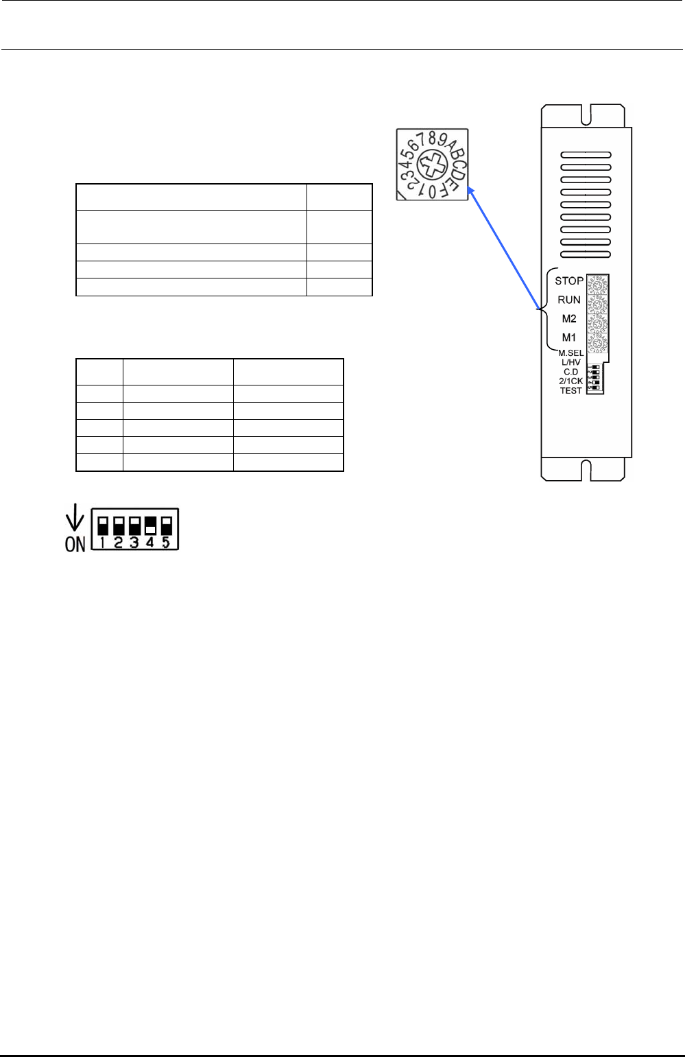
<Adjustment Procedure for Machines Applicable to EN>
c Set the rotary switches to the values in the table below.
Rev. 1.00
Switch Settings
STOP (For support table)
STOP (For auto width adjustment)
9
5
RUN C
M2 0
M1 0
d Set the DIP switches to the values in the table below.
No. Switch Settings
1 TEST OFF
2 2/1CK OFF
3 C.D OFF
4 L/HV ON
5 M.SEL OFF
Figure 13-7-3-2-4 DIP SW
Switch lever positions
When the switch is flipped down, it is
turned ON. On the contrary, when the
switch is flipped up, it is turned OFF.
Figure 13-7-3-2-3 DIP SW
FX-3R Maintenance Guide
13-47
13-8. Head Unit
13-8-1. Adjusting the Boards of the Head Unit
13-8-1-1. Adjusting the Head Main Board Assembly
See “Head Vacuum Level and Temperature Sensor Output Level” on page 1-10 for the QA table.
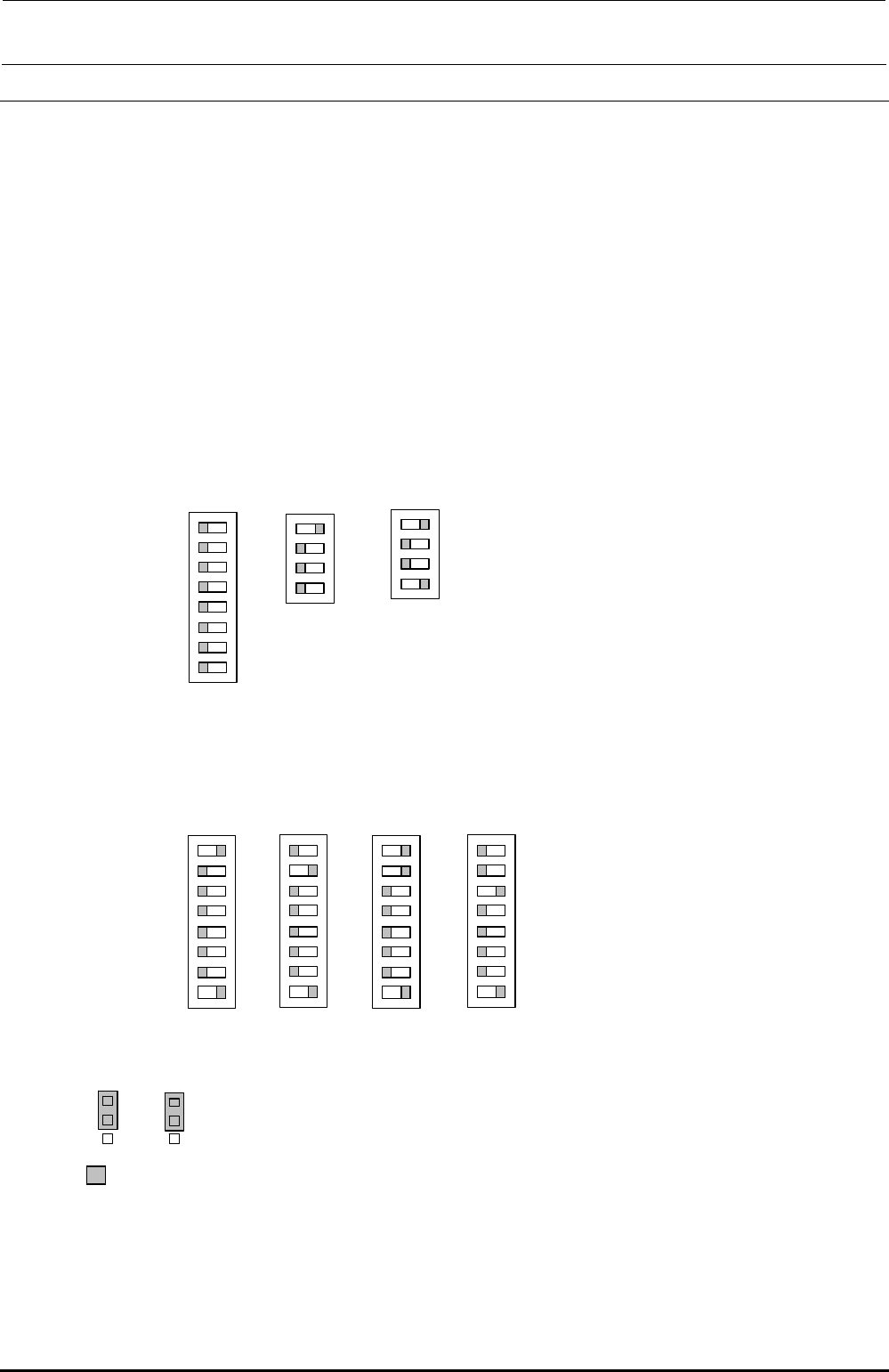
13-8-1-1-1. Switch Settings
The switches have already been set corresponding to the status of the board assembly. Check
the contents described below.
Additionally, the SW4 settings may vary depending on the head position. Set the SW4
corresponding to the head position.
・
SW1, SW2, SW5
・
SW3
・
SW4
・
W4, W5
Check that the W4, W5 are set as described below.
*
portion shows the switch set position and receptacle mounting position.
Check that the SW1, SW2, SW5 are set as described below.
Function Rev. and pattern Rev. of the board are set on the SW 2. Normally, do not change the switch
settings.
The SW4 setting may vary depending on the head position. Check that this switch is set as follows
according to the heat position.
O
N
1
SW1
2
3
4
5
6
7
8
O
N
1
SW2
2
3
4
SW4
O
N
1
2
3
4
5
6
7
8
LF
O
N
1
SW4
2
3
4
5
6
7
8
L
R
O
N
1
SW4
2
3
4
5
6
7
8
R
F
O
N
1
SW4
2
3
4
5
6
7
8
RR
O
N
1
SW5
2
3
4
W4
1
2
3
W5
1
2
3
Rev. 1.00