fx3r.pdf - 第43页
FX-3R Maintenance Guide 3-11 3-5. Replacing the Head Board 3-5-1. Replacing the Head Main Board 1) Remove the round screws c ( × 6) and clamps d ( × 2) to detach the main cover. 2) Disconnect various connectors and remov…
FX-3R Maintenance Guide
3-10
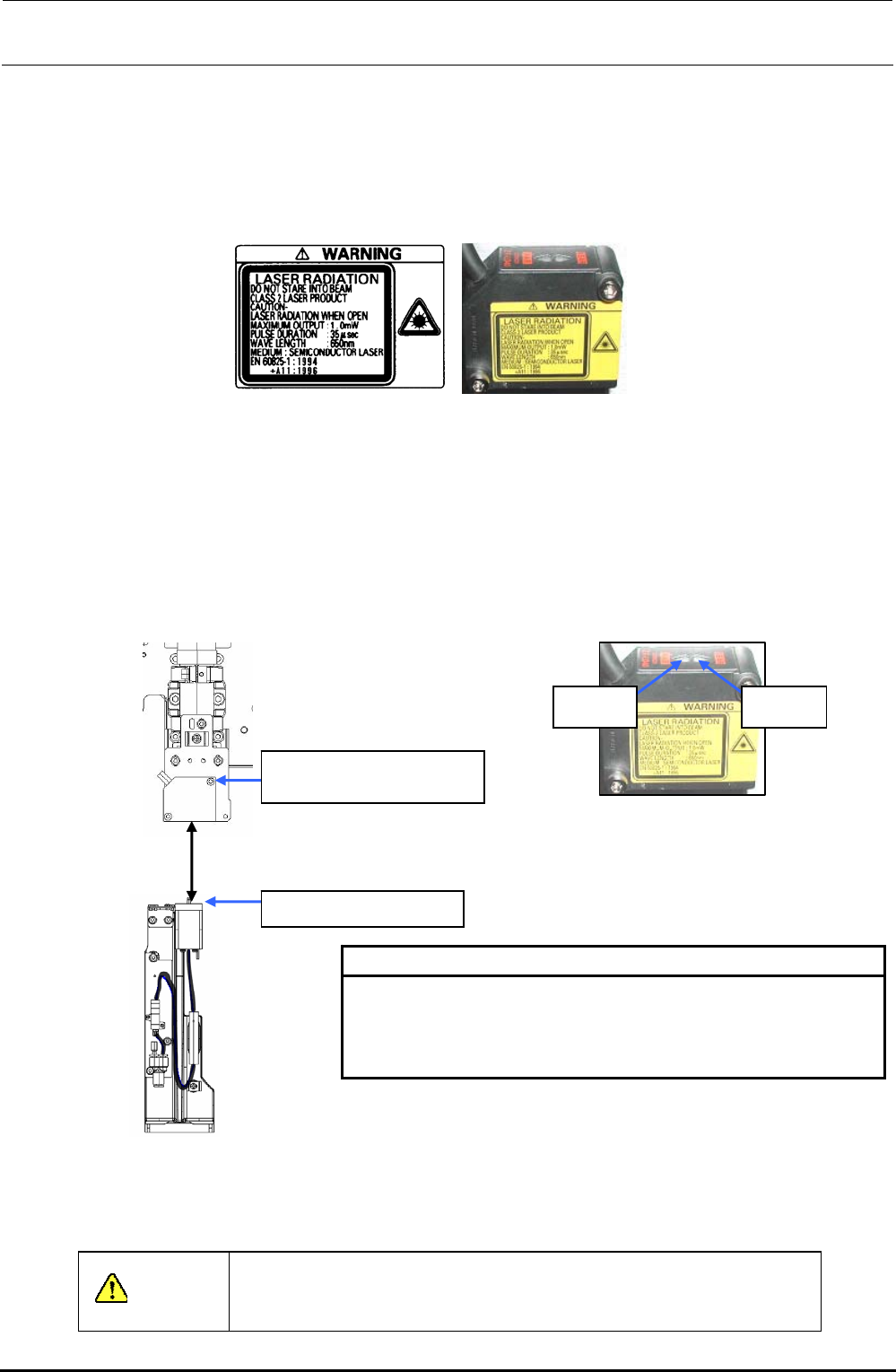
3-4-3. Sticking the Label
After the label sticking surface has been degreased, stick the label. (The following Figure shows the
LF and RR heads.)
The LR and RF heads have the cable running direction opposite to that of the LF and RR heads.
Stick the label in an orientation so that it can be seen from the front.
Figure 3-4-3-1 Amplifier Replacement (Left: Label/Right: Label Stuck)
3-4-4. Adjusting the HMS Height
Move the HMS sensor to a point above the calibration block. Loosen the SEMS cap bolts c at two
locations and adjust the distance between the bottom surface of the height sensor and the top
surface of the calibration block to a specified value of 40 ± 0.2 mm. At this time, check that both the
FAR and NEAR indicators are lit. After the distance has been adjusted to a specified level, secure
the height sensor with the SEMS cap bolts c at two locations.
NEAR
indicator
FAR
indicator
c SM6032002TN
SEMS cap bolt M3×20
CAL block top surface
40
±
0.2mm
[HMS sensor range indicator: lighting status]
NEAR/FAR Both are lit : Measurement center distance ±1 mm
NEAR Lit : Near distance side within measurement range
FAR Lit : Far distance side within measurement range
NEAR/FAR Both are flashing : Beyond measurement range
Figure 3-4-4-1 Adjusting the HMS Height
After the sensor height has been adjusted, input the MS parameters related to the bad mark sensor
offset. For details about how to input MS parameters, see “MS Parameters”.
CAUTION
To prevent any personal injury, do not put your hand inside the
machine or your face or head close to the machine during operation
of the touch panel and/or HOD.
Rev. 1.00
FX-3R Maintenance Guide
3-11
3-5. Replacing the Head Board
3-5-1. Replacing the Head Main Board
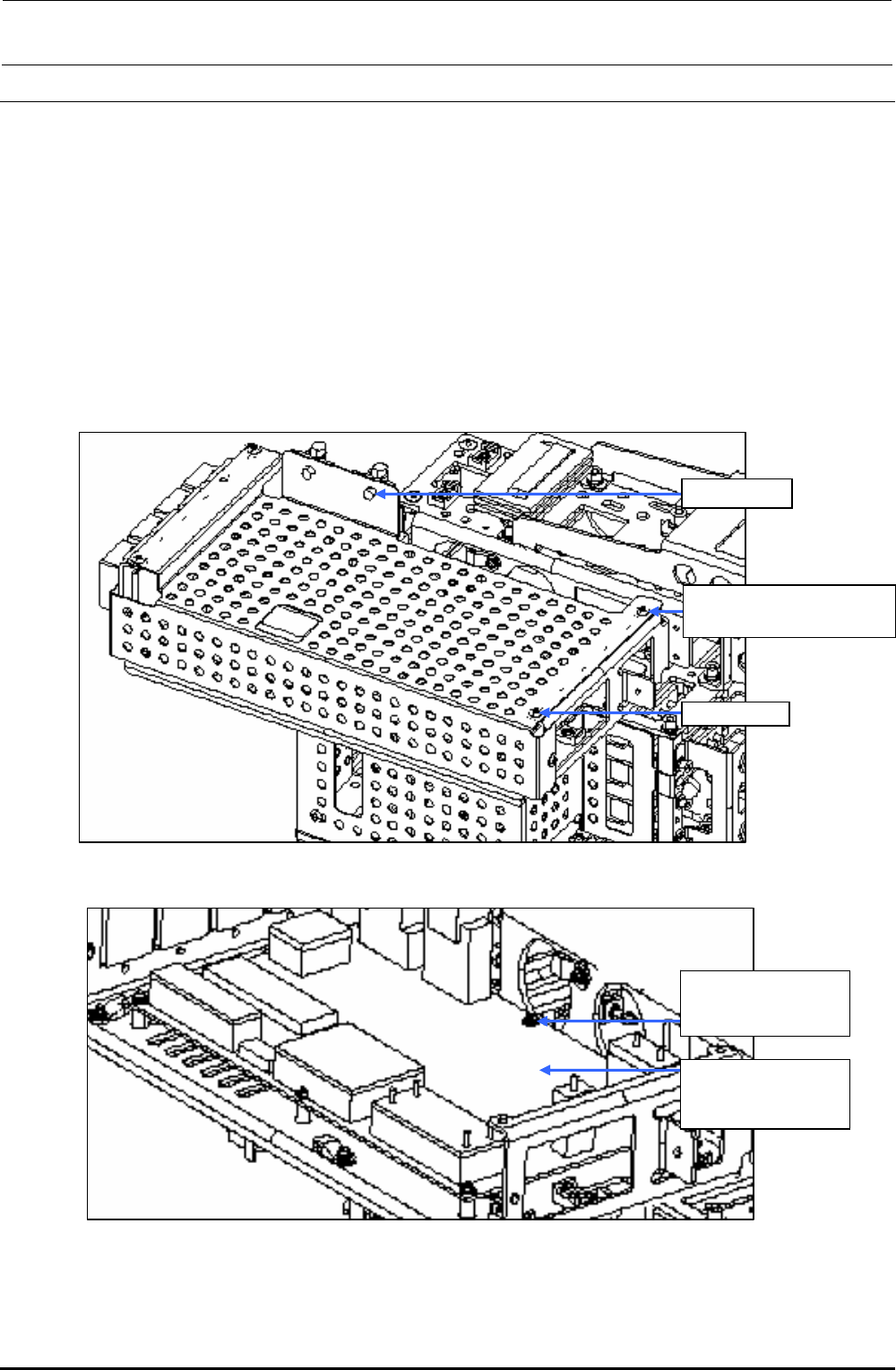
1) Remove the round screws c (×6) and clamps d (×2) to detach the main cover.
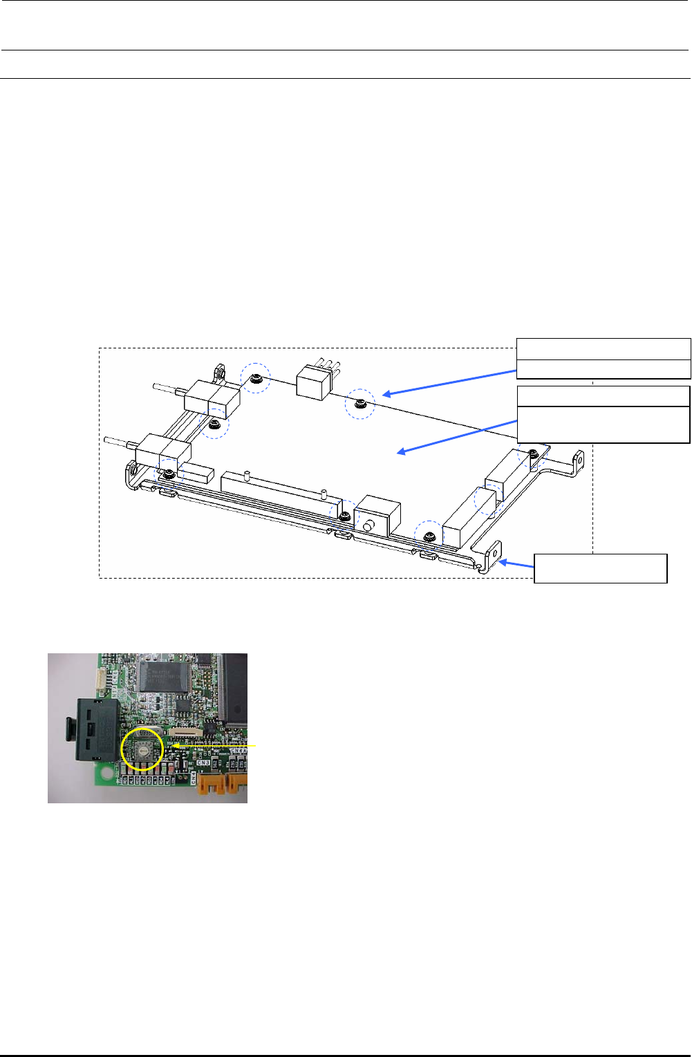
2) Disconnect various connectors and remove the SEMS cap bolts e (×6) to detach the head
main board.
3) Reassemble the parts and components in the reverse order of disassembly.
Since the head main board is delivered after it has been adjusted correctly, no adjustment work
is required.
∗ Follow the steps stated in“Head Vacuum Level and Temperature Sensor Output Level”on
page 1-4 for the QA table, only if any fault is found.
c SM3040652TN
Round screw M4×6
Clamp d
Main cover
Figure 3-5-1-1 Main Cover
e SL4030691SC
SEMS cap bolts
M3×6
40047506
Head main board
assembly
Figure 3-5-1-2 Replacing the Head Main Board
Rev. 1.00
FX-3R Maintenance Guide
3-12
3-6. Replacing the ZT-Driver Board
3-6-1. Replacing the ZT-Driver Board
1) Refer to section 2-1, “Replacing the Head Unit”, and steps 1) to 6), 14), and 16) in “Adjustment
after replacement” of Chapter 2.
2) Remove the SEMS cap bolts c (×8) from the ZT-driver support to detach the ZT-driver board.
∗ The trimmer on the ZT-driver board needs to be adjusted. Adjust the trimmer while
referring to section 13-6, Z-θ Unit
3) Reassemble the parts and components in the reverse order of disassembly.
c SL4030691SC
SEMS cap bolts M3×8
40044535
4-axis integrated type
servo amplifier
ZT-driver support
Figure 3-6-1-1 Replacing the Driver Board
Trimmer
Rev. 1.00