fx3r.pdf - 第73页
FX-3R Maintenance Guide 5-20 Rev. 1.00 [List of Replacement Parts] Table 5-13-2 Reference for PWB Positioning Hole Part No. Part name Part No. Part name 1 ∗ 1 PV150209000 5-PORT SOLENOID VALVE 7 ∗ 1 PV150209000 5-PORT SO…
FX-3R Maintenance Guide
5-19
Rev. 1.00
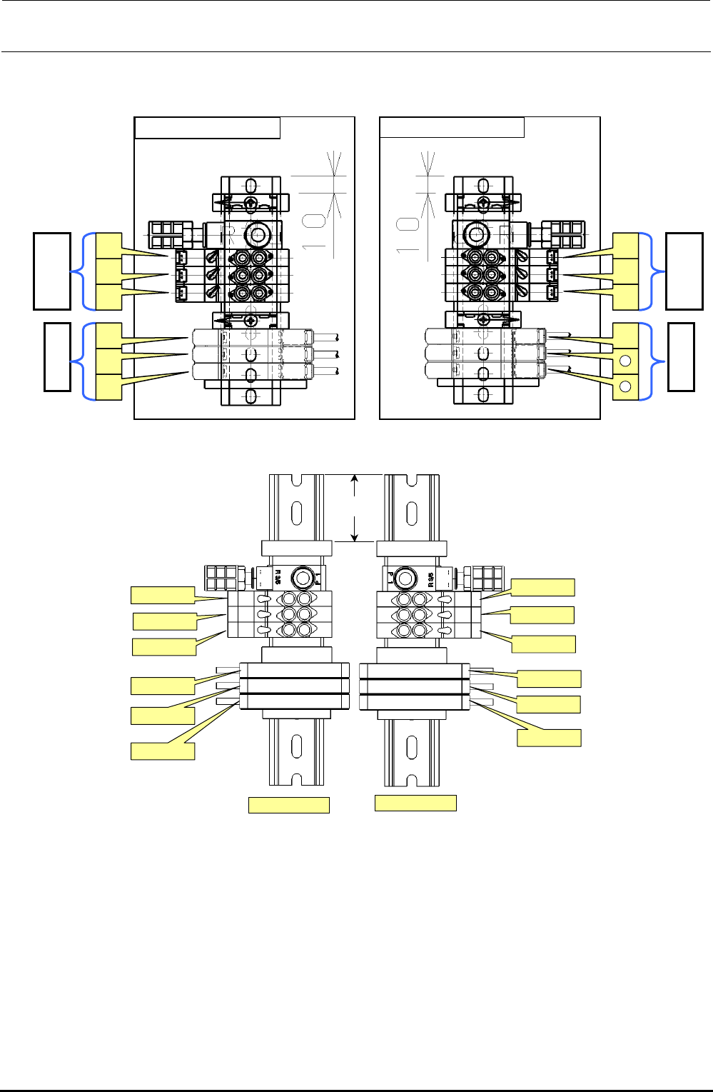
For details about how to replace the parts and connect the cables and piping inside the solenoid
valve assembly, see Figure 5-13-2.
Figure 5-13-2 Solenoid Valve Assembly L Specification
43mm
C-OUT
STOP
WAIT
STOPPER
SHAPE Y
BU(EN)
BU(EN)
SHAPE Y
STOPPER
C-OUT
WAIT
STOP
搬送ユニット L用
搬送ユニット R用
Figure 5-13-3 Solenoid Valve Assembly XL Specification
Amplifier
Solenoid
v
a
lv
e
d
[For transport unit L] [For transport unit R]
c
e
f
g
h
j
i
k
l
11
12
Amplifier
Solenoid
v
a
lv
e
For transport unit L
For transport unit XL

FX-3R Maintenance Guide
5-20
Rev. 1.00
[List of Replacement Parts]
Table 5-13-2 Reference for PWB Positioning Hole
Part No. Part name Part No. Part name
1∗
1
PV150209000
5-PORT SOLENOID VALVE
7∗
1
PV150209000
5-PORT SOLENOID VALVE
2 PV150209300
5-PORT SOLENOID VALVE
8 PV150209300
5-PORT SOLENOID VALVE
3 PV150209300
5-PORT SOLENOID VALVE
9 PV150209300
5-PORT SOLENOID VALVE
4 40047772 WAIT-L SENSOR ASM 10 40047775 WAIT-R SENSOR ASM
5 40047774 STOP-L SENSOR ASM 11 40047777 STOP-R SENSOR ASM
6 40047773 COUT-L SENSOR ASM 12 40047776 COUT-R SENSOR ASM
∗
1
In the case of EN type, a solenoid valve (PV150209000) is provided in addition to those
provided as the standard specifications.
∗
2
In the figure, BU(EN), SHAPE Y, and STOPPER are solenoid valves; WAIT, STOP, and
C-OUT are sensor amplifiers.
FX-3R Maintenance Guide
5-21
Rev. 1.00
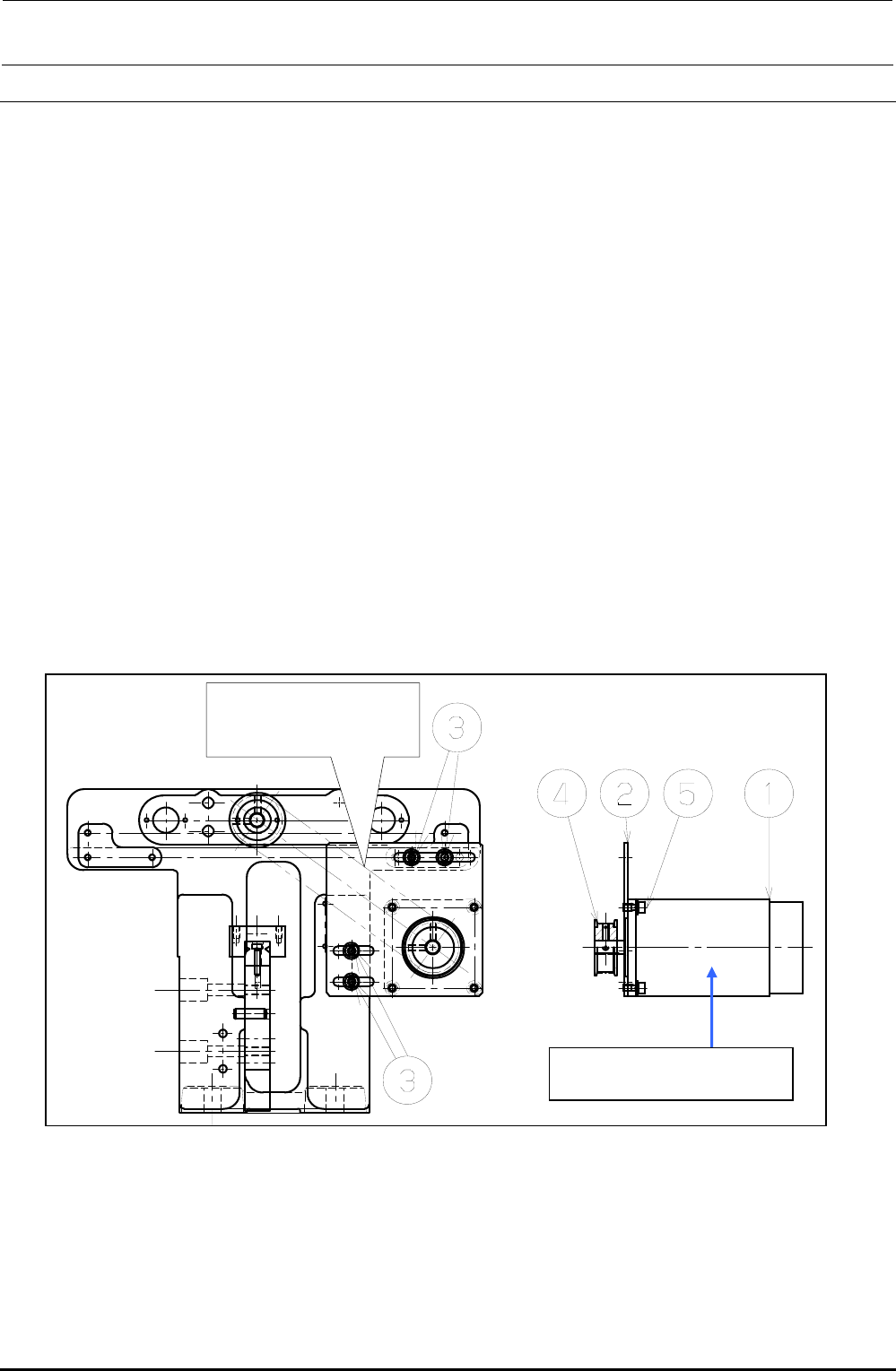
5-14. Auto PWB Width Adjustment
5-14-1. Replacing the AWC Motor
1) Disconnect the connectors of the motor relay cable.
2) Loosen the set screws e on the motor bracket d to detach the drive belt from the motor pulley
f.
3) Loosen the motor set screws g to detach the motor c.
4) Detach the motor pulley f from the motor.
5) Reassemble the components in the reverse order of steps 1) to 4). At this time, assemble the
components so that the end face of the motor shaft is aligned with the end face of the pulley f.
6) Adjust the tension of the drive belt.
• Belt tension adjustment procedure
Measure the tension at the center of the belt (see the Figure below) with UNITTA's belt tension
meter.
c Values to be input to tension meter Weight: 002.5
Width: 009.0
Span: 0133
d Adjustment value 25± 2.5N⋅m
Figure 5-14-1-1 AWC Motor
Measure the belt tension
at this position with the
tension meter.
c E94347290A0
AWC Motor Assembly