fx3r.pdf - 第122页
FX-3R Maintenance Guide 11-1 DANGER To prevent any trouble caused by accidental machine start, always shut-down the power before starting the maintenance and adjustment work. [1 1] REPLACING AND ADJUSTING THE FEEDER FLOA…
FX-3R Maintenance Guide
10-6
1) Detach the switch panels from the front and rear sides. (Front, screws at 2 locations, Inside of
cover, screws at 2 locations)
2) Detach the operation board.
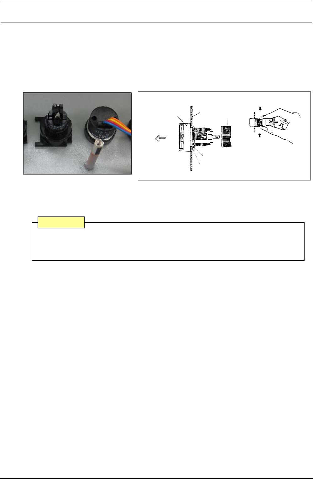
3) To detach the switch, remove the root part (mounting nut) of the switch from the back of the
cover and pull out the case from the cover surface.
4) Reassemble the components in the reverse order of disassembly.
Turn.
Turn.
Mounting
nut
Edge
Panel
Case
Groove
Pull out.
Stop metal fitting
Figure 10-4-3 Back of Cover Figure 10-4-4 Detaching the Switch
∗ The list of replacement parts is described in section 13-9-3.
A combination of the switch connector and connector on the operation switch board has
a specified orientation. Always pay special attention to the orientation when mounting
the switch.
CAUTION
Rev. 1.00

FX-3R Maintenance Guide
11-1
DANGER
To prevent any trouble caused by accidental machine start, always
shut-down the power before starting the maintenance and
adjustment work.
[11] REPLACING AND ADJUSTING THE FEEDER FLOAT SENSOR
(1) In the FX-3R, the sensors are arranged as shown in the Figure below.
If the sensor is detached together with the bracket, it becomes necessary to adjust the sensor
height.
When replacing only the sensor, start the sensor replacement work from step (4).
Top view of mounter
Front
Rea
r
Rear left
Front right
Rear right
Rear left
Rear right
Front left
Front left Front right
Receiving
Emitting
Receiving
Emitting
Receiving
Emitting
Receiving
Emitting
Receiving
Emitting
Receiving
Emitting
Receiving
Emitting
Receiving
Emitting
(Outside of machin
(Transport passage si
e)
de)
(Transport passage si
(Outside of machin
de)
e)
Figure 11-1 Layout of Feeder Float Sensors
Rev. 1.00
FX-3R Maintenance Guide
11-2
Rev. 1.00
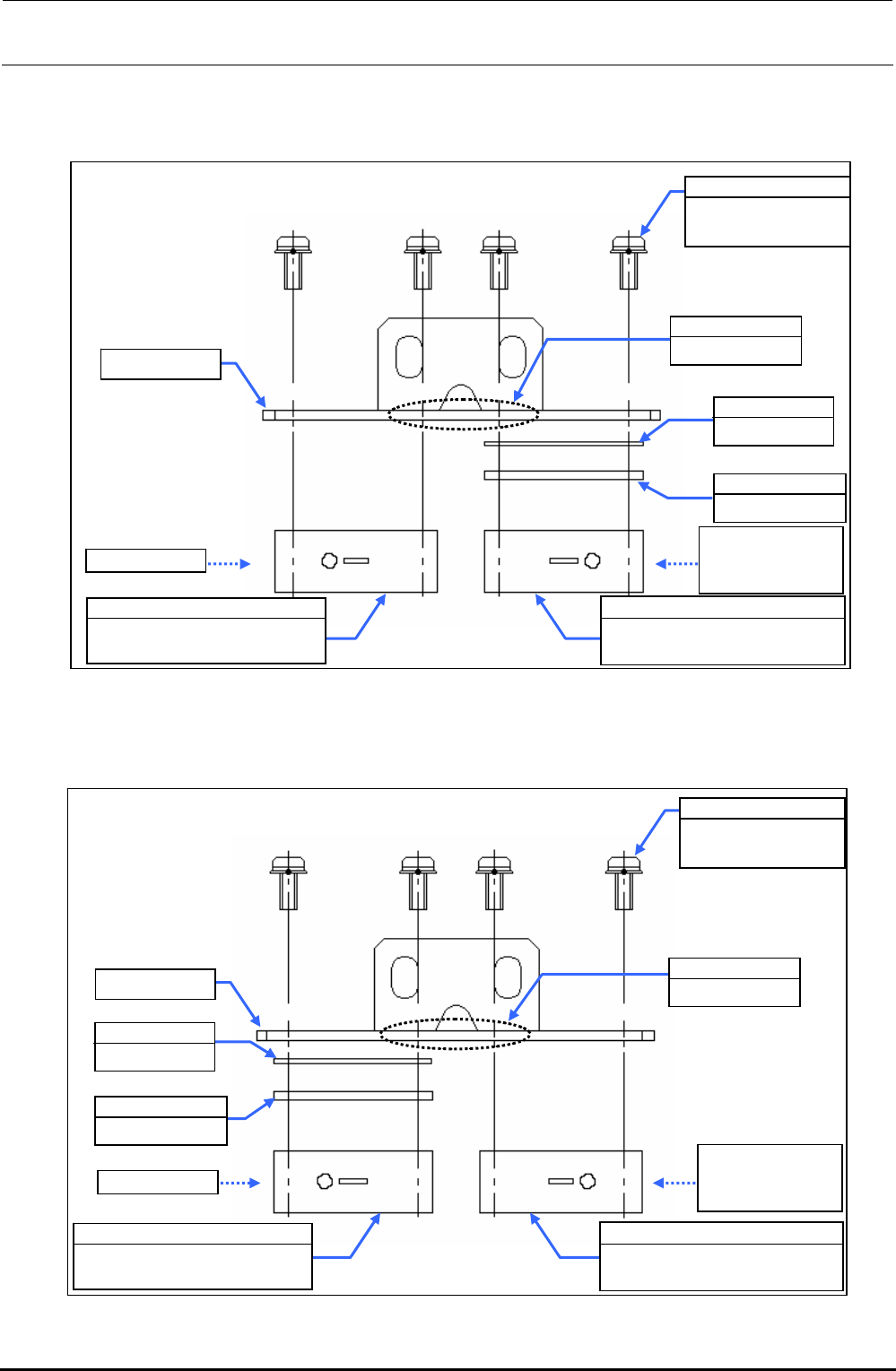
2) Replace the sensor in the detached bracket assembly with a new one.
c FSD bracket assembly (front left portion)
Figure 11-2 FSD Bracket Assembly (Front Left Portion)
d FSD bracket assembly (front right portion)
Figure 11-3 FSD Bracket Assembly (Front Right Portion)
SL4031481SC
SEMS cap bolt
M3×14
EA9500B0100
Tie-up band
Sensitivity
adjustment side
of check LED
40047495
Feeder float sensor (FF)
light emission assembly
FSD bracket
40001312
OCC shim C
E2157729000
FSD spacer
Check LED
40047498
Feeder float sensor (FR)
light receiving assembly
FSD bracket
SL4031481SC
SEMS cap bolt
M3×14
E2157729000
FSD spacer
40047496
Feeder float sensor (FF)
light receiving assembly
EA9500B0100
Tie-up band
Check LED
Sensitivity
adjustment side
of check LED
40001312
OCC shim C
40047497
Feeder float sensor (FR)
light emission assembly