fx3r.pdf - 第12页
FX-3R Maintenance Guide 1-4 1-1-3. Clearance of the Magnescale (1) Loosen the screws fixing the sensor and put the clearan ce jig with a thickness of 0.25 mm in the clearance between the magnescale and sensor head. (2) T…
FX-3R Maintenance Guide
1-3
Rev. 1.00
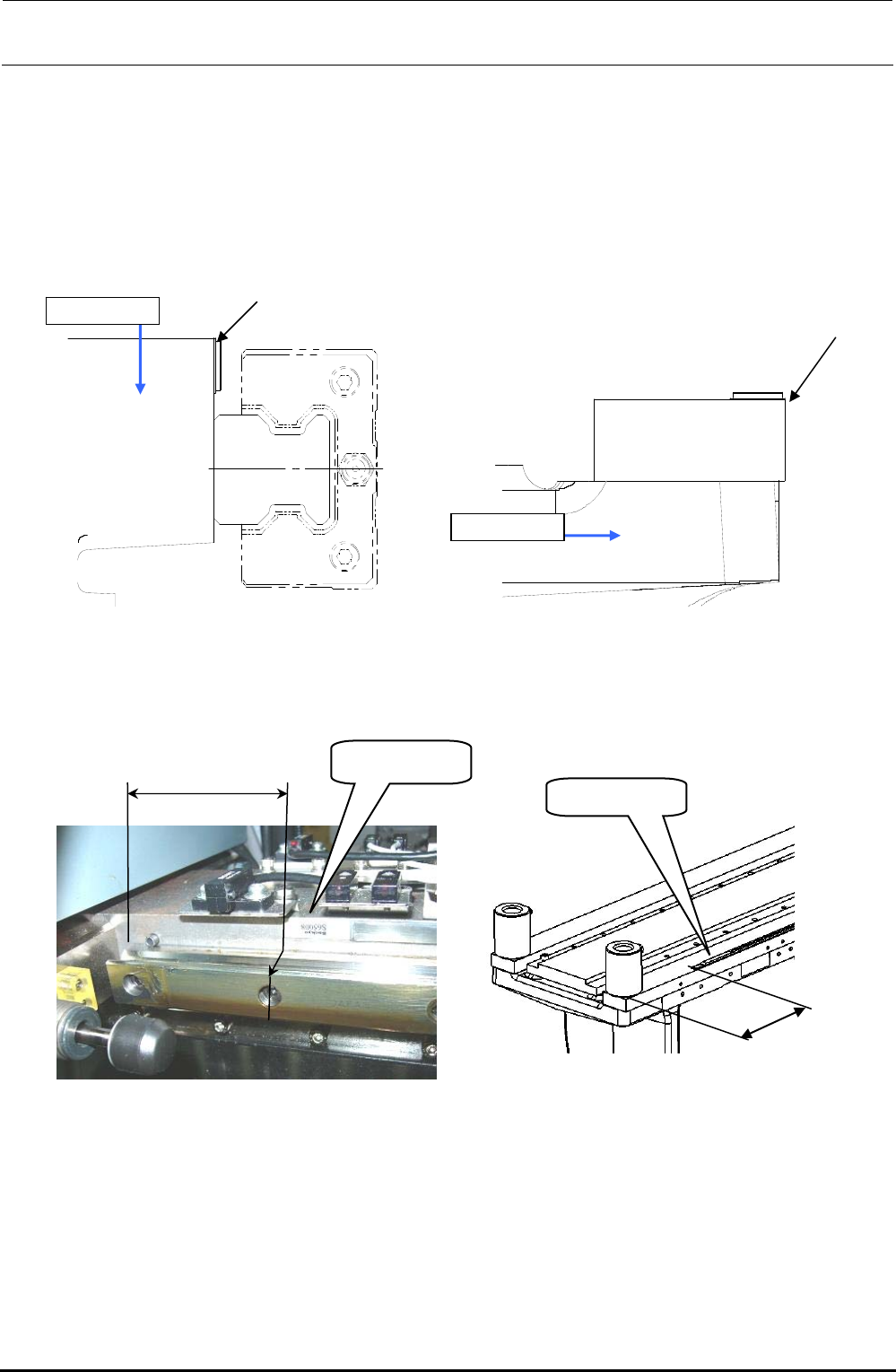
1-1-2. Y-Axis Magnescale Affixing Position
(1) Affix the magnescale while aligning the center portion with the top surface of the Y-frame C and
its side surface with the rail side surface of the Y-frame S.
Specification value: Magnescale affixing position (Displacement in the direction parallel with the
head movement) ± 0.1mm
Figure 1-1-2-1 Y-Axis Magnescale Affixing Position
(Left Figure shown above: Y-frame C, Right Figure shown above: Y-frame S)
Y-frame C
Y-frame S
Alignment with
this surface
Alignment with
this surface
Label side
72±1mm
Figure 1-1-2-2 Y-frame C Affixing Position
Figure 1-1-2-3 Y-frame S Affixing Position
115±1mm
Label side
FX-3R Maintenance Guide
1-4
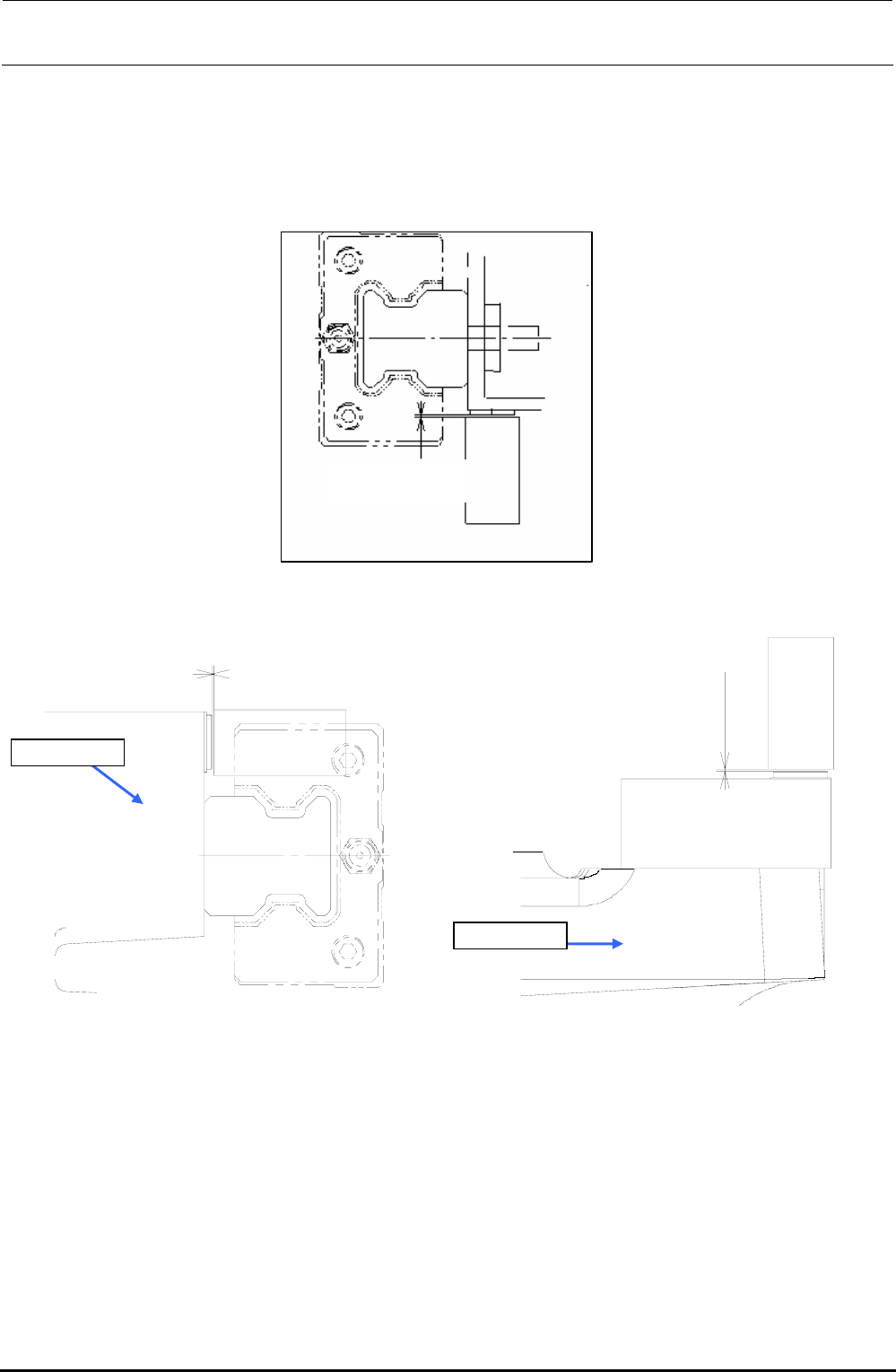
1-1-3. Clearance of the Magnescale
(1) Loosen the screws fixing the sensor and put the clearance jig with a thickness of 0.25 mm in
the clearance between the magnescale and sensor head.
(2) Tighten the set screws of the sensor head to remove the clearance jig with a thickness of
0.25±0.1 mm.
0.25±0.1mm
Figure 1-1-3-1 X-Axis Side
0.25 ± 0.1 mm
0.25 ± 0.1 mm
Y-frame C
Y-frame S
Figure 1-1-3-2 Y-Axis Side
1-1-4. Re-obtaining the Parameters after Replacement of the Magnescale
Follow the work steps stated in section 2.3, Y Setup of the MS parameters to obtain the offset
amount of the right origin position to the left origin position.
Make the correction so that the machine status becomes the factory-settings.
∗ “Y Setup” operation is performed based on the preconditions that the mechanical squareness
has been adjusted completely.
If the mechanical squareness deviates, it is necessary to adjust the mechanical squareness.
(See “X/Y Unit” in the QA Table.)
Rev. 1.00
FX-3R Maintenance Guide
1-5
1-2. Replacing the Limit Sensor and Origin Near Sensor
(1) When replacing only the sensor, it is not necessary to adjust the position.
(2) When replacing the sensor together with the bracket, it is necessary to adjust the position.
∗ The home position of the X-axis is the Z-phase of the magnescale. Therefore, there is no home
position sensor for the X-axis.
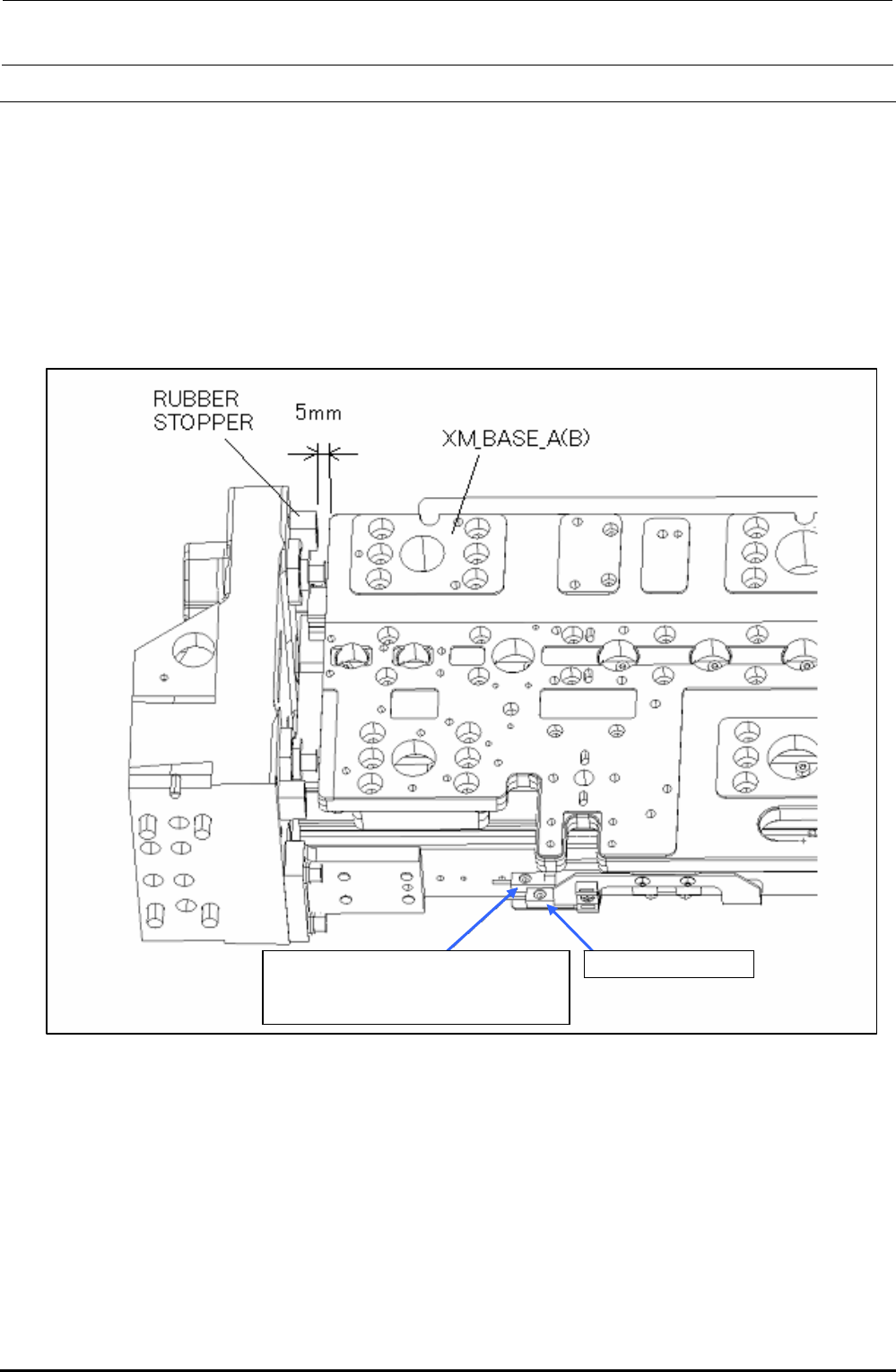
1-2-1. Replacing the X+/− Limit Sensor and X-Near Sensor
X NEAR SENSOR X +LIMIT SENSOR
(X -LIMIT SENSOR is located on
the right of the X-axis.)
Figure 1-2-1-1 Adjusting the Sensors on the X-Axis
(1) When the distance between each rubber stopper and the XM base A (or B) becomes 5 mm,
make the adjustment so that each limit sensor is turned ON, and then secure each limit sensor
with the screws.
Rev. 1.00