fx3r.pdf - 第92页
FX-3R Maintenance Guide 8-10 8-2-3. Adjusting the Speed C ontroller of the Drive Cylinder The following describes how to adjust the up speed of the drive cylinder. Rev. 1.00 1) Detach the drive cylinders to be adjusted f…
FX-3R Maintenance Guide
8-9
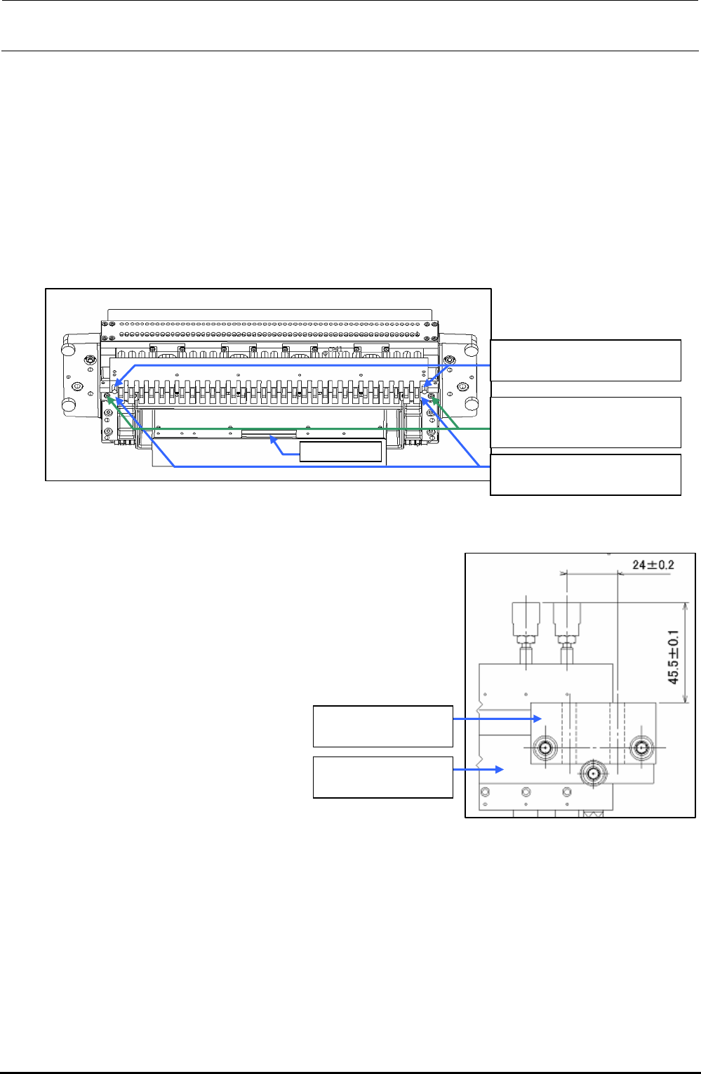
8-2.2. Replacing the Drive Cylinder
1) Turn OFF the power to the main unit completely before starting the replacement work.
2) Shut-down the main pressure air to the main unit (with the hand valve). If the machine is
equipped with an optional replacement table, disconnect the air tube and move the
replacement table outside the main unit.
3) Disconnect the left and right air tubes and connectors.
4) Remove the driver bracket mounting screws.
BT0600400EC
Air tube φ6
40047249
Drive bracket
SL6053092TN
SEMS cap bolt with washer
M5×30
Connector
Figure 8-2-2-1 Part Names (When Viewed Slantwise from the Lower Portion)
5) Replace the drive cylinder with a new one and mount the
driver bracket (30) and drive bracket.
For details about assembly and adjustment work, see the
Figure on the right.
6) Reassemble the components in the reverse order of
disassembly.
40047249
Drive bracket
E2708729000
Driver bracket (30)
Figure 8-2-2-2 Drive Bracket Assembly Positions
Rev. 1.00
FX-3R Maintenance Guide
8-10
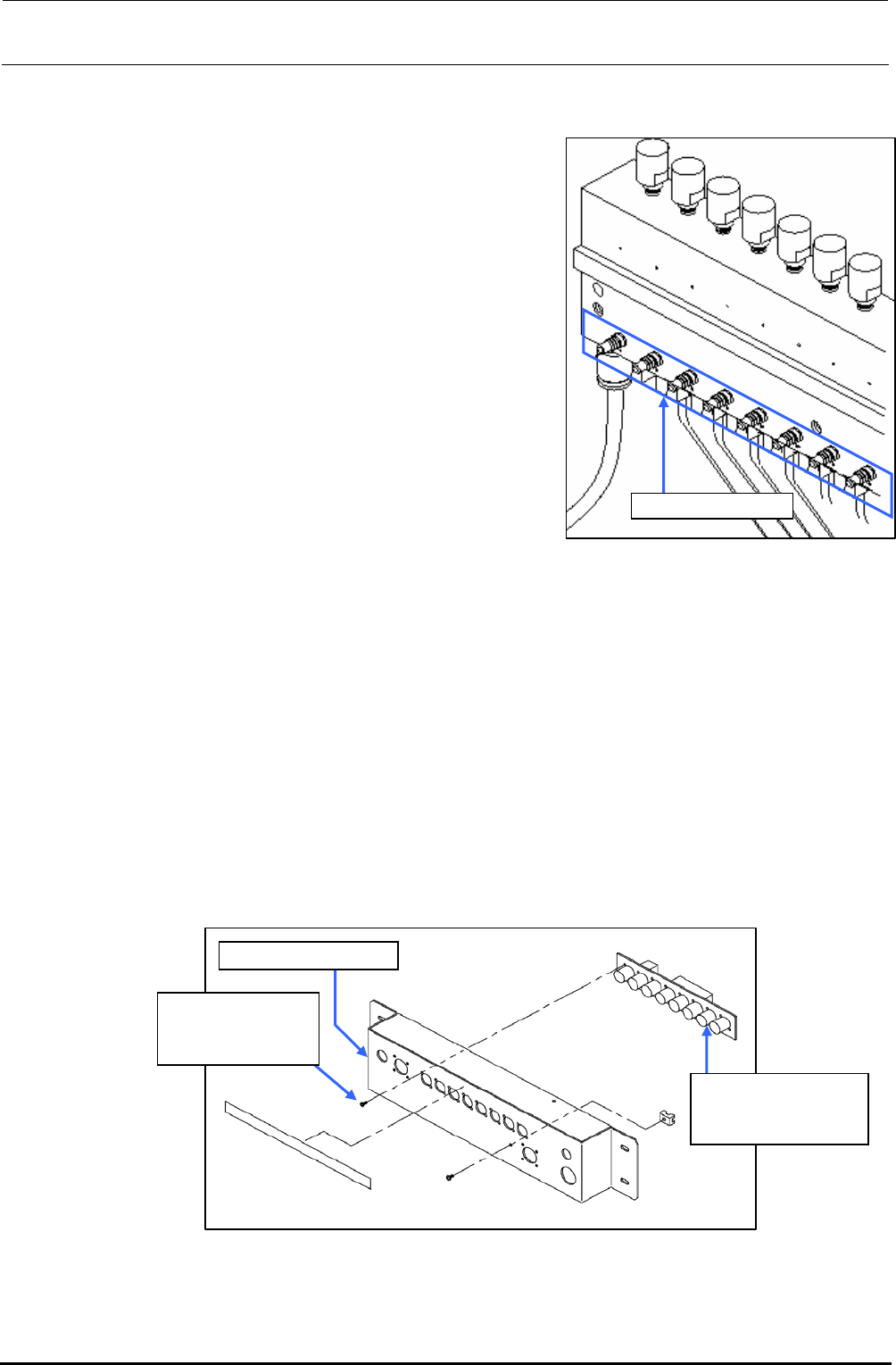
8-2-3. Adjusting the Speed Controller of the Drive Cylinder
The following describes how to adjust the up speed of the
drive cylinder.
Rev. 1.00
1) Detach the drive cylinders to be adjusted from the
driver bracket.
2) Connect the air tube and connector.
3) Supply the main compressed air and turn on the
power.
4) Using the manual control, operate all drive cylinders
continuously, the speed controller of which needs to
be adjusted.
5) Adjust the speed controller of the cylinder to be
adjusted visually so that the movement of the cylinder
is the same as that of other cylinders.
6) Tighten the nut of the speed controller firmly. After the
nut has been secured, recheck that the cylinder
functions correctly.
Figure 8-2-3-1 Speed Controller of
Drive Cylinder
Speed controller
7) Reassemble the components in the reverse order of
disassembly.
8-2-4. Replacing the Feeder Bank Board (Optional)
1) Disconnect the connector bracket IF cable, connector bracket PWR cable.
2) Remove the mounting screws to detach the connector bracket.
3) Disconnect the connectors from the feeder bank board.
4) To detach the feeder bank board, remove eight round head screws. After relevant board has
been detached, replace it with a new one.
5) Reassemble the components in the reverse order of disassembly.
Connector bracket
E86157150A0
Feeder bank board
assembly
SM4860601SC
Round head screw
M2.6×6
Figure 8-2-4-1 Feeder Bank Board Related Part Names
FX-3R Maintenance Guide
8-11
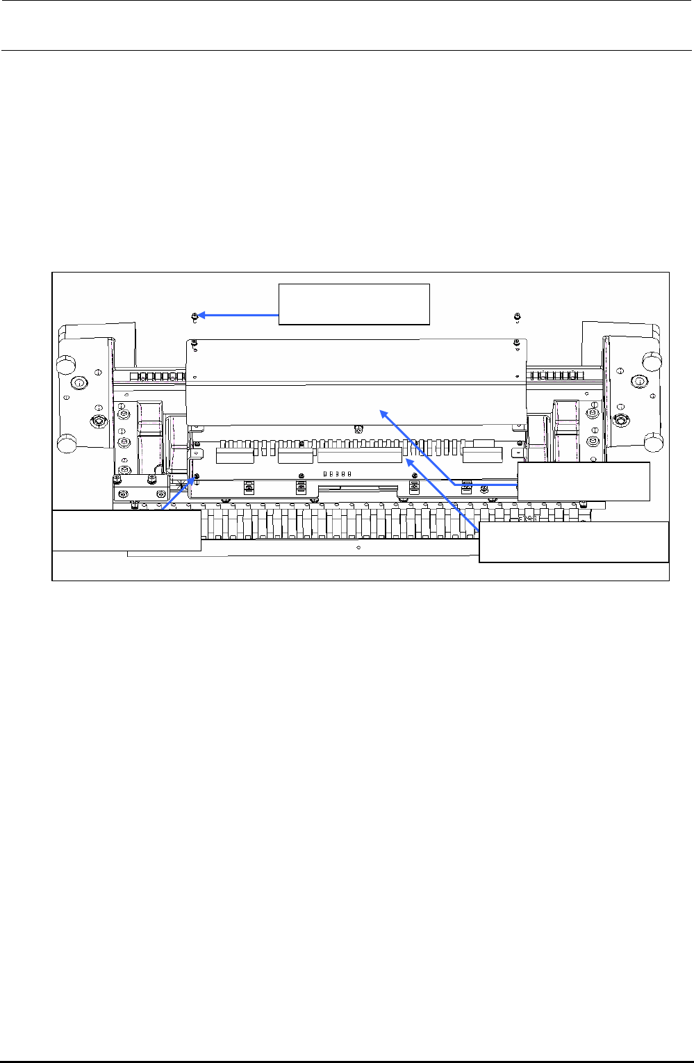
8-2-5. Replacing the Bank PCB
1) Remove the mounting screws to detach the front panel.
2) Disconnect the connectors (cables) from the mechanical bank PCB.
3) Remove the round head screws (8 pcs.) to detach the mechanical bank PCB and replace it with
a new one.
4) Reassemble the components in the reverse order of disassembly.
SL6030692TN
SEMS cap bolt M3×6
40047311
Front panel
40082808
Mechanical bank PCB ASM
SL4030681SC
SEMS cap bolt M3×6
Figure 8-2-5-1 Bank PCB (When Viewed Slantwise from the Lower Portion)
Rev. 1.00