fx3r.pdf - 第204页
FX-3R Maintenance Guide 13-35 Transport direction: Sensor layout for L → R IN BUFFER L-STATION JOINT BUFFER R-STATION OUT BUFFER IN/OUT-L WAIT-L COUT-L STOP-L WAIT-R COUT-R STOP-R IN/OUT-R T ransport direction: Sensor la…
FX-3R Maintenance Guide
13-34
13-7. Transport Unit
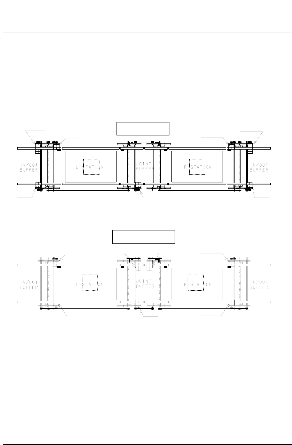
13-7-1. Structure of Transport Unit
Table 13-7-1-1 shows the structure drawing of the transport unit.
The BASE-CARRY board is mounted at the front right portion under the base frame and the driver
for the stepping motor (for transport, auto PWB width adjustment, and backup) is mounted at both
the front left and right portions.
It is not necessary to change the connection destination boards of the transport L motor, transport
R motor, transport L sensor, transport R sensor, and WAIT sensor inside the transport unit
according to the reference and flow direction.
BU モータ L BU モータ R
L specification
XL specification
BU モータ L BU モータ R
Trans
p
ort moto
r
AWC motor L
(For L-STA)
Transport motor
(For IN/OUT)
(For joint)
Transport motor
(For R-STA)
AWC motor R
Transport motor
(
For IN/OUT
)
Transport motor
BU motor L BU motor R
[F side]
[F side]
BU モータ L BU モータ R
Trans
p
ort moto
r
AWC motor L
(For L-STA)
(For IN/OUT)
(For joint)
Transport motor
(For R-STA)
(For IN/OUT)
BU motor L
BU motor R
AWC motor R
Transport motor
Transport motor
Transport motor
Figure 13-7-1-1 Transport Unit
Rev. 1.00
FX-3R Maintenance Guide
13-35
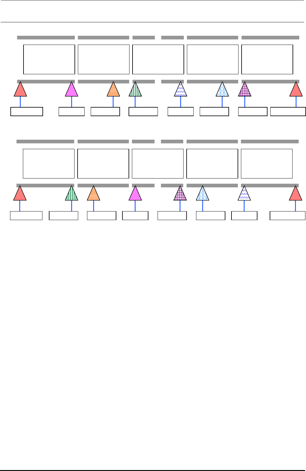
Transport direction: Sensor layout for L→R
IN BUFFER
L-STATION
JOINT BUFFER
R-STATION
OUT BUFFER
IN/OUT-L WAIT-L COUT-LSTOP-L WAIT-R COUT-R STOP-R IN/OUT-R
Transport direction: Sensor layout for R→L
IN BUFFER
L-STATION
JOINT BUFFER
R-STATION
OUT BUFFER
IN/OUT-L WAIT-LCOUT-L STOP-L WAIT-R COUT-R STOP-R IN/OUT-R
Figure 13-7-1-2 Structure of Transport Unit
Rev. 1.00
FX-3R Maintenance Guide
13-36
Rev. 1.00
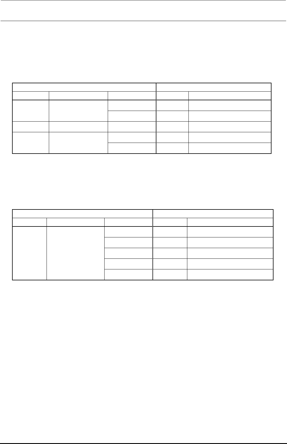
[Connections of transport motor]
The following Table shows each mounting position and connection cable from the left to the right
when viewed from the front of the machine.
Table 13-7-1-1 Connections of Transport Motor
• L specification
Motor Connection cable
Part No. Part name Mounting position
Part No. Part name
IN (L-end) 40047807 IN-MOTOR CABLE ASM
40048074 ∗1 CENTER MOTOR ASM
CENTER L 40047805 CENTER-MOTOR (L) CABLE ASM
40048075 ∗2 JOINT MOTOR ASM JOINT 40047808 JOINT-MOTOR CABLE ASM
CENTER R 40047806 CENTER-MOTOR (R) CABLE ASM
40048074 ∗1 CENTER MOTOR ASM
OUT (R-end) 40047809 OUT-MOTOR CABLE ASM
∗1 The transport motor was changed from the motor (E93417290A0) and these motors have the interchangeability.
∗2 The transport motor was changed from the motor (E93408550A0) and these motors have the interchangeability.
• XL specification (In the XL specification, the JOINT motor for the L specification is used for
the CENT motor and IN/OUT motor.)
Motor Connection cable
Part No. Part name Mounting position
Part No. Part name
IN (L-end) 40089913 IN-MOTOR CABLE ASM
CENTER L 40089911 CENTER-MOTOR(L) CABLE ASM
JOINT 40089914 JOINT-MOTOR CABLE ASM
CENTER R 40089912 CENTER-MOTOR(R) CABLE ASM
40048075 JOINT MOTOR ASM
OUT (R-end) 40089915 OUT-MOTOR CABLE ASM