fx3r.pdf - 第237页
FX-3R Maintenance Guide 15-3 Rev. 1.00 15-2. Replacing the Tape Cutter Main Unit 1) With the cutter blade closed, close the finger valve to shut down the air to the ma chine main unit. 2) Disconnect the air tube from the…
FX-3R Maintenance Guide
15-2
Rev. 1.00
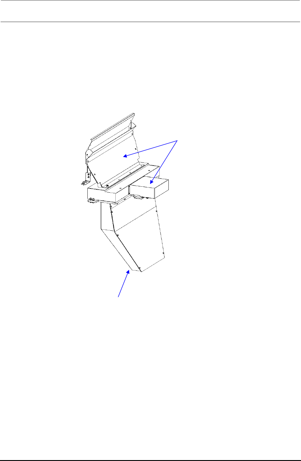
15-1-1. Tape Cutter for Electric Fixed Bank Specification
The lower discharge guide shape of the cutter for the electric fixed bank specification is different
from that for the replacement table specification.
Tape cutter for electric fixed bank specification
Lower discharge guide shape: This shape is different from the cutter for the
replacement table specification.
Upper discharge guide and cutter
main unit are the same as the
cutter unit for the replacement table
specification.

FX-3R Maintenance Guide
15-3
Rev. 1.00
15-2. Replacing the Tape Cutter Main Unit
1) With the cutter blade closed, close the finger valve to shut down the air to the machine main
unit.
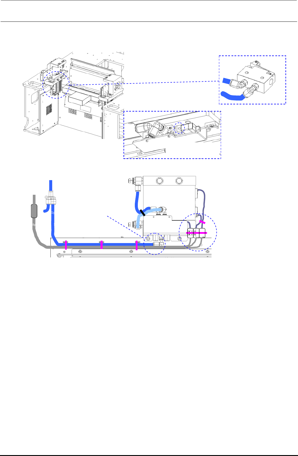
2) Disconnect the air tube from the air cylinder and the cable connector from the solenoid valve.
3) Remove the upper discharge guide. (This guide is assembled to the base frame and cutter
base.)
4) Remove the lower discharge guide. (This guide is assembled to the cutter base and main unit
bottom cover.)
5) Remove the cutter main unit mounting screws to replace the cutter main unit.
∗ Disconnect the joint and blind plug from the air tube of those connected to the cylinder of
the cutter for replacement and connect it to the solenoid valve (B port).
6) Reassemble the components in the reverse order of disassembly.
7) Assemble the shim and spacer used for the cutter main unit mounting part in the same manner
as the original manner.
8) Make the upper discharge guide in contact with the opening in the cutter cover (push toward
you) to assemble it.
9) For the replacement table specification, after the upper discharge guide has been assembled,
check that the top end of the bank does not interfere with the guide in the trolley set status
(bank down status). If the top end interferes with the guide, adjust the trolley height.
10) Mount the electric bank on the machine main unit (bank up status) and set the electric feeder
(ETF). At this time, check that the clearance between the tape discharge port (top end of ETF)
of the ETF and the tape guide is 2±0.5 mm. If this clearance is beyond the standard value,
loosen the cutter main unit screws and upper discharge guide screws, and adjust the
clearance.
11) Assemble the lower discharge guide while referring to section 15-2-1, Assembling and
Adjusting the Lower Discharge Guide.
FX-3R Maintenance Guide
15-4
Rev. 1.00
Figure 15-2-1 Disconnection of Air Tube and Solenoid Valve Connector
Mechanical valve
Solenoid valve
Manual switch
CN381
Solenoid valve connector
connection
Air tube connection