fx3r.pdf - 第67页
FX-3R Maintenance Guide 5-14 Rev. 1.00 5-11. Replacing the Support Table Motor (BU Motor) 1) Remo ve the support table as descr ibed below. 1. Stretch the transport width as much as possible. 2. Remove 12 ( ∗ ) pan head …
FX-3R Maintenance Guide
5-13
Rev. 1.00
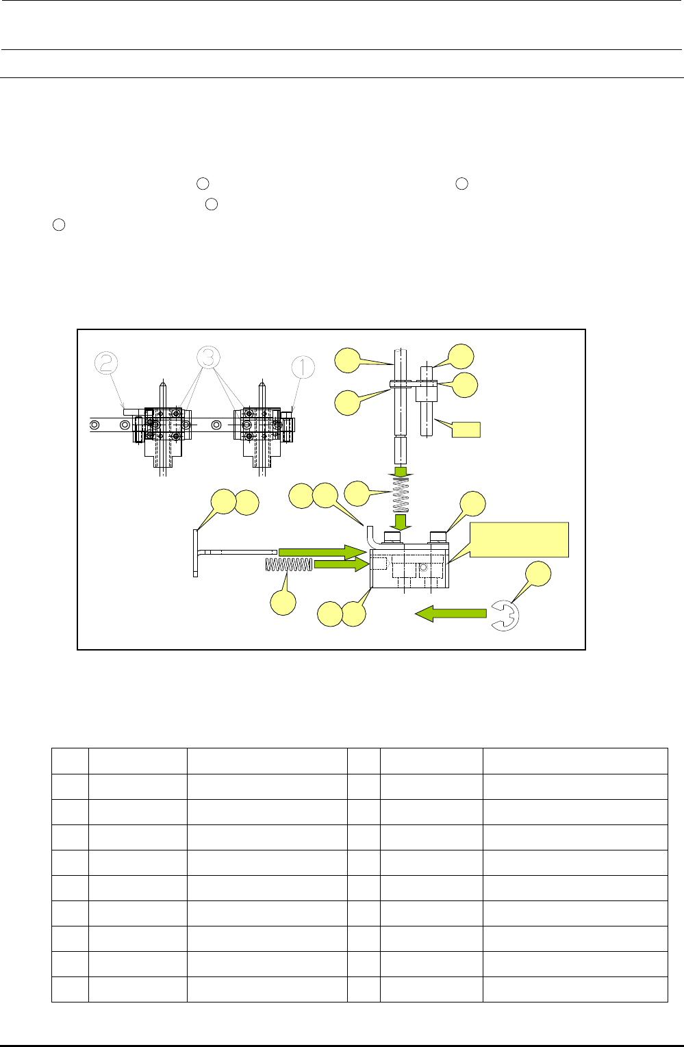
5-10. Replacing the Centering Pin (Optional)
1) Loosen the screws c, d and e of the guide block A and guide block B to detach the centering
pin together with the guide blocks.
2) At this time, also detach the T-PIN sensor (together with its bracket) from the reference side.
Removing the E ring
12
allows you to pull the centering pin
17
from the damper block.
Removing the E rings
16
(two in total, top and bottom) allows you to remove the centering pin
17
.
When installing a new centering pin, reassemble the components in the reverse order. The
E-rings must also be replaced with new ones.
After the components have been reassembled, adjust the sensor position in the same manner
as described in 5-10, Replacing the T-PIN Sensor.
Figure 5-10-1 Centering Pin
Table 5-10-1 Reference for PWB Positioning Hole
[List of Replacement Parts]
Part No. Part name
Part No. Part name
1 40000886 GUIDE_BLOCK_ASM 10
40000895 DAMPER_BLOCK_R
2 40000887 GUIDE_BLOCK_A_ASM 11
SL6030892TN SCREW
3 40000889 GUIDE_BLOCK_B_ASM 12
RE0300000K0 E-RING
4 40000891 STOPER_SLIDE_LEVER_L 13
40000896 DAMPER_LOCK_PIN
5 40000897 STOPER_SLIDE_LEVER_R
14
40000978 DAMPER_LOCK_LINK
6 40000892 DAMPER_BLOCK_L 15
40000950 DAMPER_SPRING
7 40015791 DAMPER_PLATE_L 16
RE0300000K0 E-RING
8 40015792 DAMPER_PLATE_R 17
40001081 CENTERING_PIN 4.0
9 40015793 LOCK_SPRING
⑦
④
⑰
⑬
⑭
⑯
A
⑤
⑨
⑮
⑧
⑪
B部
右側=⑧+⑩+⑪
左側=⑦+⑥+⑪
⑫
⑩⑥
Section B
Right side = ⑧+⑩+⑪
Left side = ⑦+⑥+⑪
FX-3R Maintenance Guide
5-14
Rev. 1.00
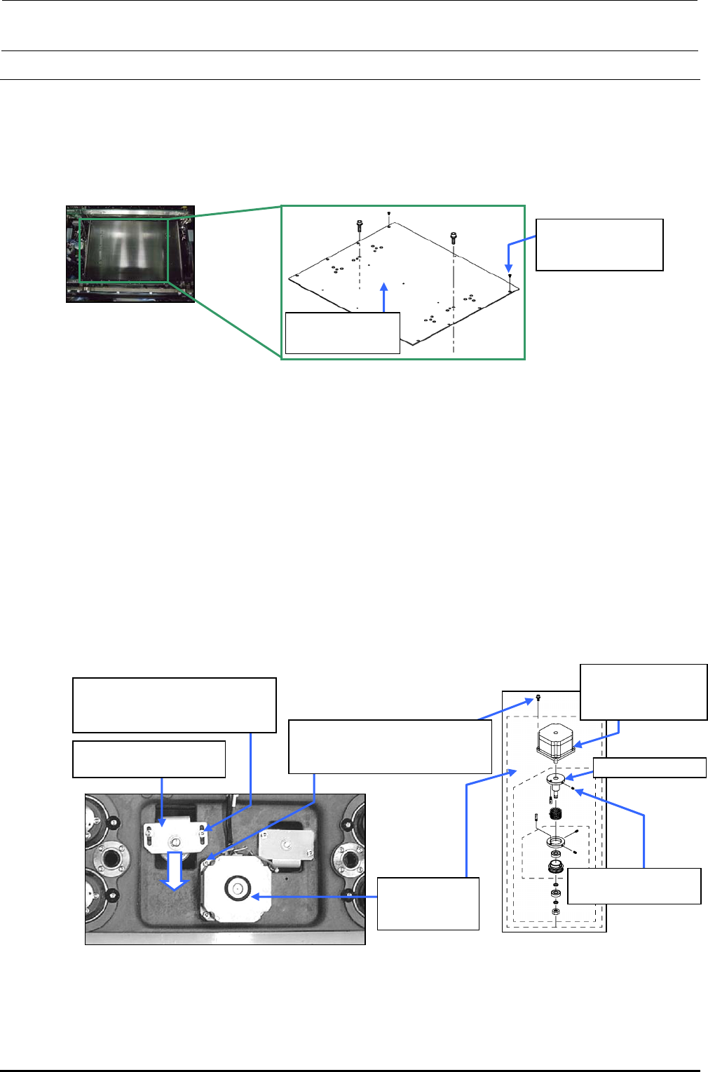
5-11. Replacing the Support Table Motor (BU Motor)
1) Remove the support table as described below.
1. Stretch the transport width as much as possible.
2. Remove 12 (∗) pan head screws d from the support table c to detach the table.
∗ For the number of screws, the L-specification uses 12 pcs. while the XL-specification
uses 14 pcs.
Figure 5-11-1 Support Table
2) Loosen the tension support fixing screw f, and move the tension support assembly e in the
arrow direction to loosen the tension of the support table ball screw driving timing belt
3) Loosen the set screws h to take out the support table BU motor assembly g together with the
torque support.
4) Loosen the set screws i to detach the torque support assembly from the shaft of the BU motor
j.
5) Assemble the parts and components in the reverse order of above steps 1) to 3). When
assembling the parts and components, perform the following adjustments.
• Adjust the gap between the torque support and BU motor assembly. (section 5-11-1)
• Adjust the tension of the support table driving timing belt. (section 5-11-2)
• Place the support table surface horizontally. (section 5-11-3)
• Obtain the support table offset. (section 3-11 in MS Parameter)
Figure 5-11-2 Support Table Drive System
Figure 5-11-3 BU Motor Assembly
c 40001018
BU table (L)
d SM1040801SN
Flat head screw
M4×8
f SL6051492TN
SEMS cap bolt with washer
M5×14
g 40000927
BU motor
assembly
h SL6051442TN
SEMS cap bolt with washer
M5×14
i SM8050852TP
Set screw M5×8
j E94327290A0
BU motor
assembly
e Tension support
assembly
Toque support
FX-3R Maintenance Guide
5-15
Rev. 1.00
5-11-1. Adjusting the Gap between Torque Supporter and Support Motor
The gap between the torque supporter and support table motor must be adjusted to 1.1 mm.
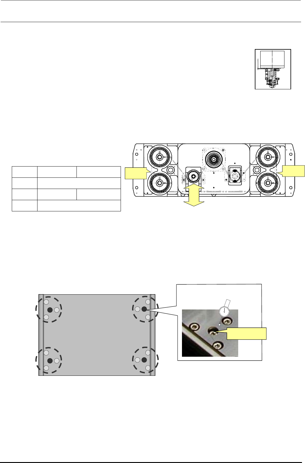
5-11-2. Adjusting the Tension of the Support Table Driving Timing Belt
To adjust the tension of the support table driving timing belt, loosen the screw of the tension
supporter assembly and move the assembly in the arrow direction, input the said values to the sonic
belt tension meter (manufactured by UNITTA), measure the tension at the locations shown below,
and then adjust the tension within the required range.
• Values to be input to the sonic belt
tension meter
L specification
XL specification
Weight 2.5
Width 9.0 12.0
Span 170
• Required range: 42.5 ± 2.5N⋅m
5-11-3. Placing the Support Table Surface Horizontally
To check flatness of the support table, attach a lever dial to the head's OCC camera bracket and
measure flatness near the center of each area circled in the figure below. Adjust the height of the
table so that the difference in flatness at the four positions is within 0.02 mm.
調節ねじ
(中央)
Figure 5-11-3-1 Measurement Locations and Adjustment Screw
Adjustment screw
(center)
Figure 5-11-2-1 Belt Tension Measurement
and Adjustment Position
Measuring
position
Weaker
Stronger
Measuring
position
Figure 5-11-1-1
Motor and Torque Supporter