fx3r.pdf - 第114页
FX-3R Maintenance Guide 9-9 <Detaching the support plate, cup packing, and suction valve interference prevention rubber> 1) Put a mark on the support plate with an oil felt pen so that it meets the mark on the casi…
FX-3R Maintenance Guide
9-8
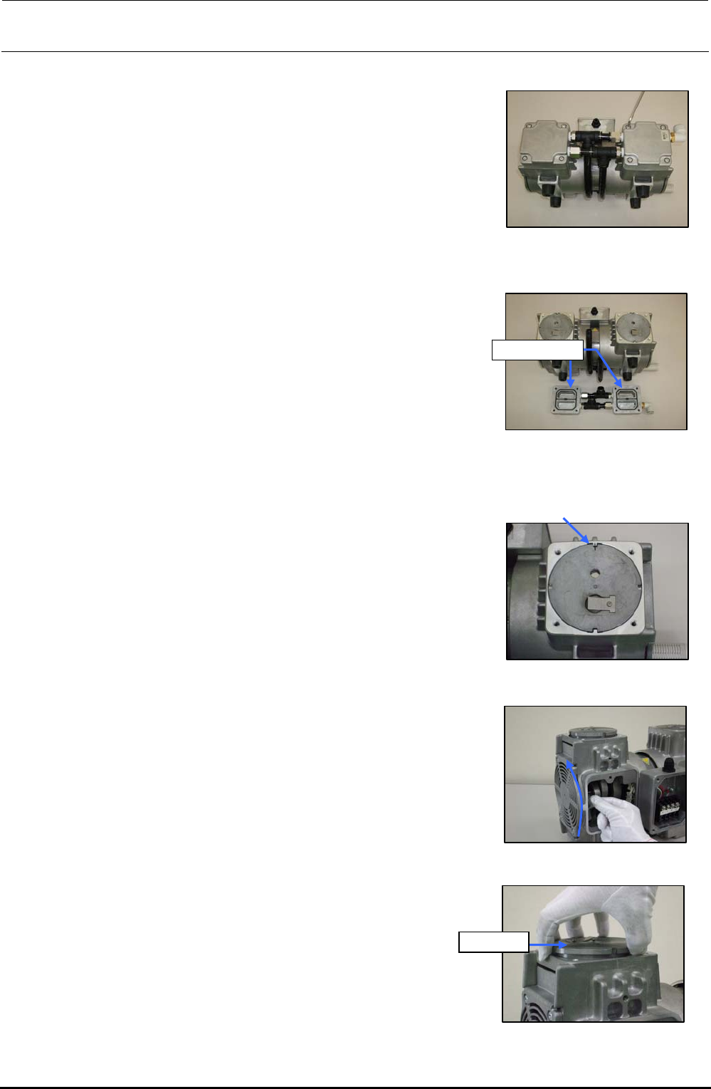
<Detaching the head cover>
1) Loosen four hexagon socket head cap bolts (M6 × L30)
fixing the head cover with an Allen wrench, and then
remove the hexagon socket head cap bolts.
Figure 9-4-5 Removing the Head
Cover Set Screws
2) Detach the head cover.
Head cover
Figure 9-4-6 Detaching the Head
Cover
<Detaching the cylinder>
1) Before detaching the cylinder, put a mark on the casing
and cylinder with an oil felt pen.
Figure 9-4-7 Putting a Mark
2) Wear gloves and gradually turn the fan upward.
(At this time, always wear gloves.)
Rev. 1.00
Figure 9-4-8 Turning the Fan
3) Pull out the cylinder upward.
Cylinder
Figure 9-4-9 Pulling Out the
Cylinder
FX-3R Maintenance Guide
9-9
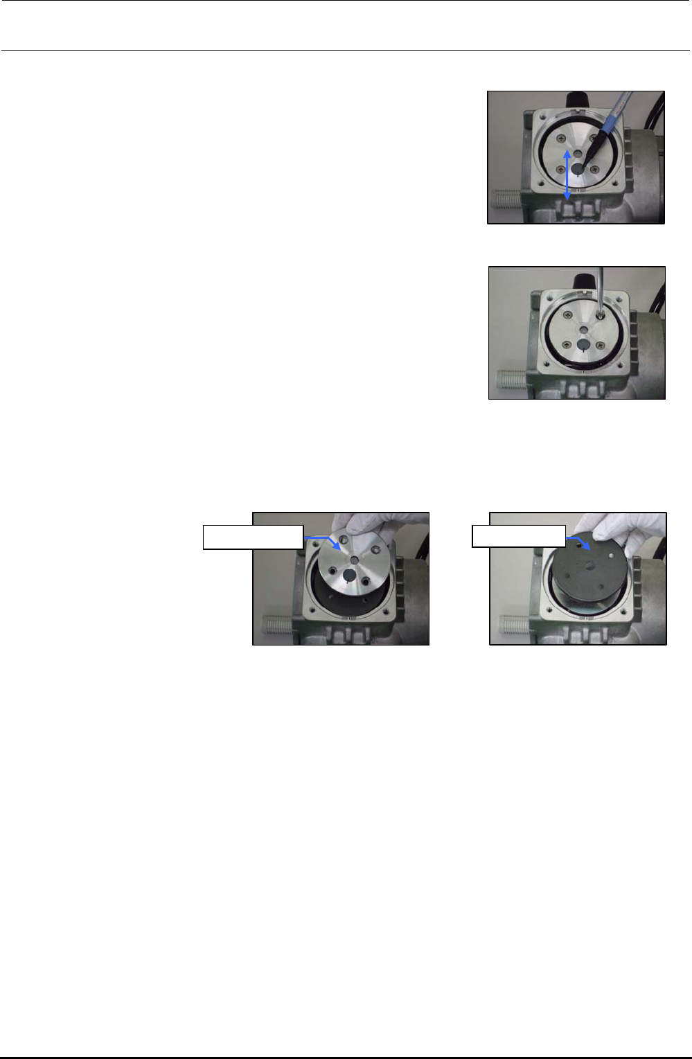
<Detaching the support plate, cup packing, and suction valve interference prevention rubber>
1) Put a mark on the support plate with an oil felt pen so
that it meets the mark on the casing.
Figure 9-4-10 Putting a Mark
2) Loosen four countersunk head screws of the support plate.
Figure 9-4-11 Removing the
Countersunk
Head Screws
3) Detach the support plate and cup packing.
Support plate Cup packing
Figure 9-4-12 Detaching the
Support Plate
Figure 9-4-13 Detaching the
Cup Packing
Rev. 1.00
FX-3R Maintenance Guide
9-10
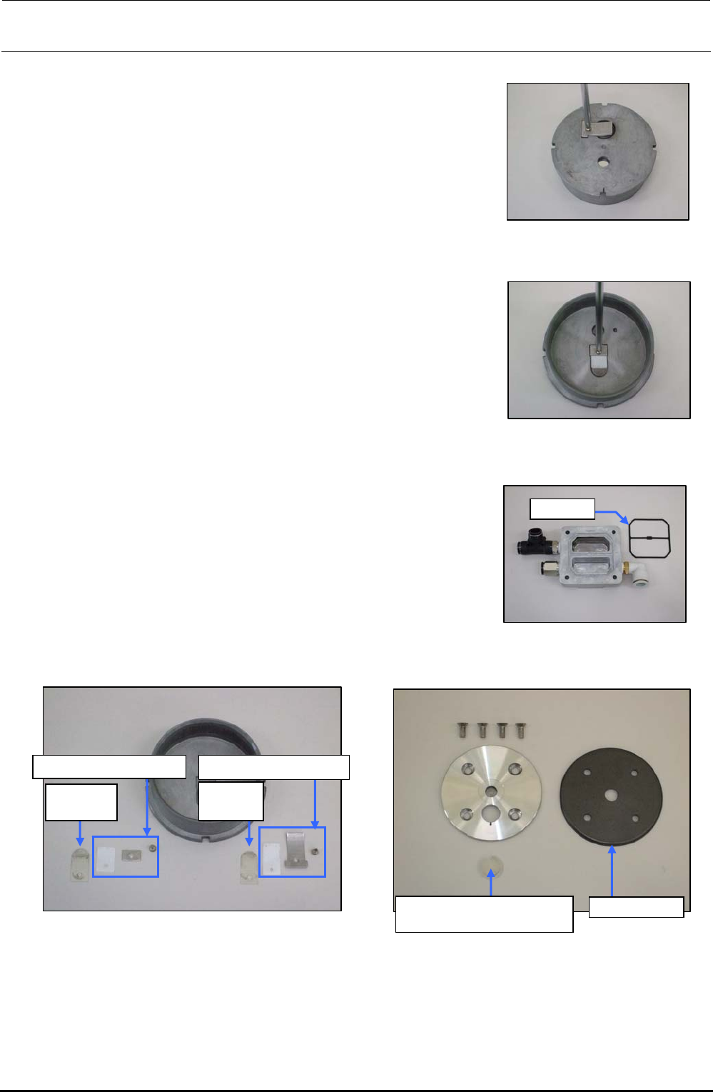
<Detaching/replacing the cylinder detailed parts>
1) Loosen the round head screws (M3 × L5) fixing the
exhaust valve support plate.
2) Detach the exhaust valve support plate, exhaust valve
backup, and exhaust valve.
Figure 9-4-14 Removing the Round
Head Screws
3) Loosen the round head screws (M3 × L5) fixing the
suction valve support plate.
4) Detach the suction valve support plate, exhaust valve
backup, and suction valve.
Figure 9-4-15 Removing the Round
Head Screws
5) Remove the gasket from the head cover and wash the
head cover. After the washing has been completed,
blow the air to the head cover and replace the gasket
with a new one.
Gasket
Figure 9-4-16 Gasket
6) Wipe off the washing solution with a cloth rag and degrease the entire cylinder completely.
Suction
valve
∗
Exhaust
valve
∗
Exhaust valve backupSuction valve backup
Suction valve interference
prevention rubber
Cup packing
Figure 9-4-17 Cylinder Figure 9-4-18 Support Plate and Cup Packing
∗ The same part is used for both the suction valve and the exhaust valve.
7) Replace each consumable part with a new one. Reassemble the parts and components in the
reverse order of disassembly so that they meet the markings. At this time, tighten the M6 bolts
fixing the head cover with a tightening torque of 8N⋅m.
Rev. 1.00