fx3r.pdf - 第126页
FX-3R Maintenance Guide 11-5 5) Adjust the volume (only the feeder float sensor). Adjust the volume after the sensor mounting height, mounting position in the Y-direction (sensor is secured to the center of the oval hole…
FX-3R Maintenance Guide
11-4
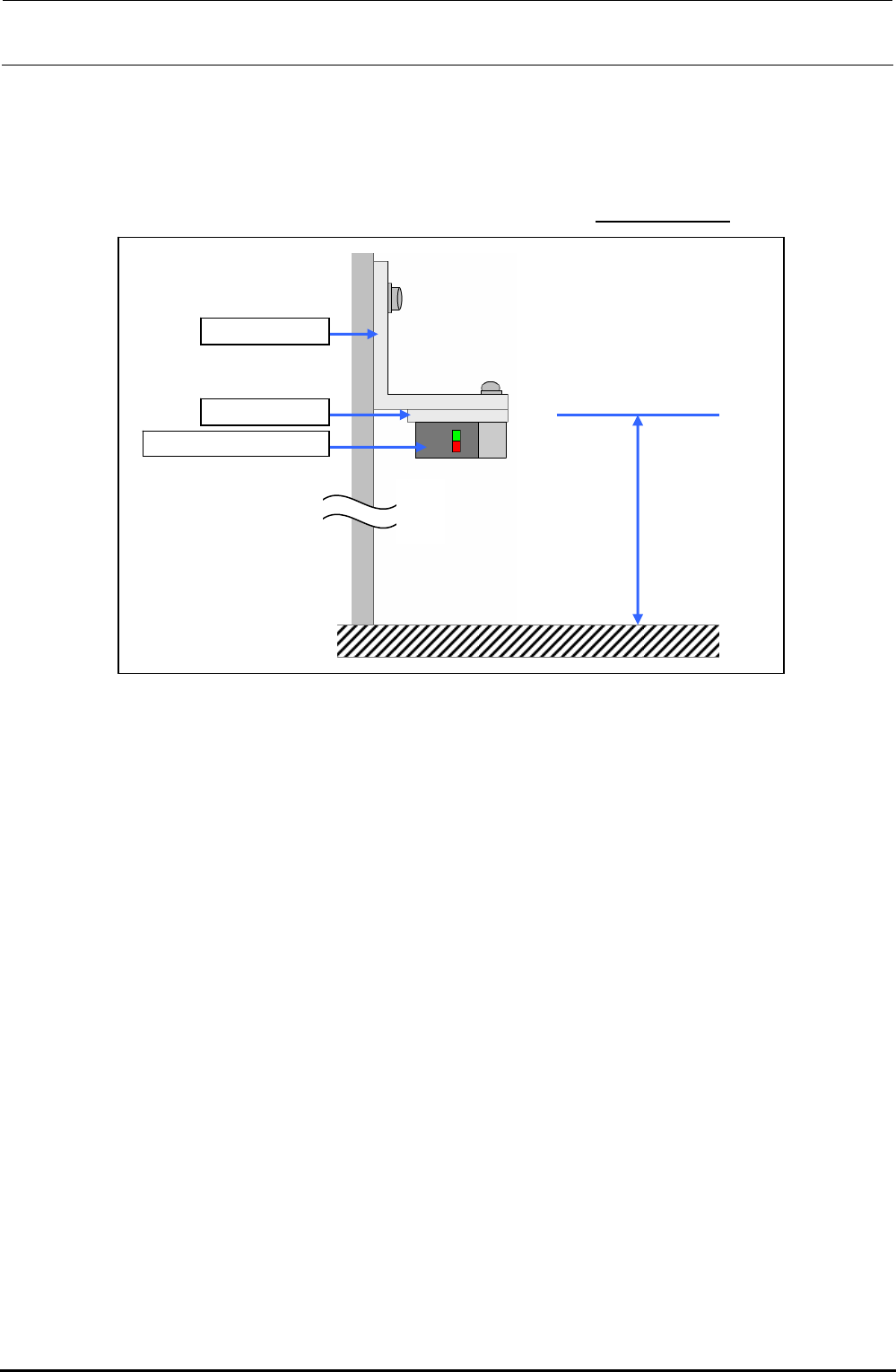
3) Adjust the height of a newly mounted sensor.
Adjust the height of the top surface of the FSD bracket to 126.6±0.1 mm from the top surface of
the feeder bank, and secure it.
However, adjust the height of the FSD bracket with a set of left and right sensors (light
receiving and light emission) so that a difference in height is
0.1 mm or less.
FSD bracket
FSD spacer
Feeder float spacer
126.6 ± 0.1mm
Figure 11-6 Adjusting the Height of the Feeder Float Sensor
4) Adjust the light axis.
c Connect the connectors of the sensors to their specified positions and turn on the power to
the main unit.
d Move the light emission and light receiving sensors so that the light axis is matched.
When the light axis is adjusted correctly, both the red and green LEDs on the light receiving
sensor will light up.
(The red LED is the operation indicator lamp and the green LED is the stability indicator
lamp.)
∗ For the FSD bracket assembly, adjust the light axis of two sensors.
Rev. 1.00
FX-3R Maintenance Guide
11-5
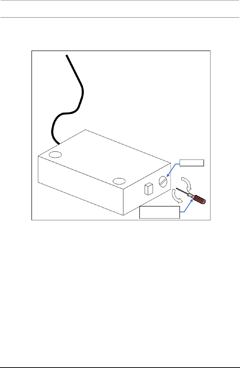
5) Adjust the volume (only the feeder float sensor).
Adjust the volume after the sensor mounting height, mounting position in the Y-direction
(sensor is secured to the center of the oval hole in the sensor bracket), and light-axis have
been adjusted.
Volume
Slotted precision
screwdriver
Figure 11-7 Adjusting the Sensitivity of the Feeder Float Sensor
<Units and tools to be used for adjustment>
• NF12 (NF16 or NF24 is also accepted.) → Non-lock type
• NF16N (NF12N or NF24N is also accepted.)
∗ The above units are used for adjustment of the feeder float sensor on the transport side.
• NF16 (NF12, NF24, NF12N, NF16N, or NF24N is also accepted.)
• NF32 feeder (NF323S, NF324S, or NF32FS is also accepted.)
• Bulk feeder (BF10, BF11, or BF12 is also accepted.)
∗ The above units are used for adjustment of the feeder float sensor outside the machine.
• Phillips screwdriver and slotted precision screwdriver
Rev. 1.00
FX-3R Maintenance Guide
11-6
c Adjusting the feeder float sensor on the transport side
1) Turn the volume on the light emission side counterclockwise to the minimum position to put the
sensor in the shut-down state.
2) Gradually turn the volume clockwise toward the maximum position and stop turning when both
the red and green lamps on the light receiving side are lit.
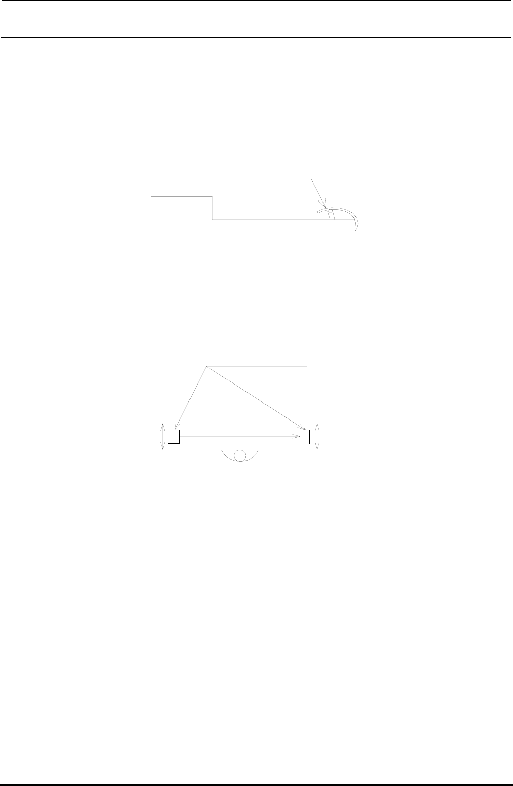
3) Set the NF12 at the left, center, and right positions of the bank. Open and close the front cover
to check that the sensor is turned OFF.
Front cover
NF12 feeder
NF16N feeder
Figure 11-8 Adjusting the Feeder Float Sensor
Move the sensor back
and forth.
Light
receiving
(Transport side)
Light
emission
Figure 11-9 Adjusting the Feeder Float Sensor
∗ If the sensor is not turned OFF even though the font cover is opened, the sensor mounting
position may deviate in the Y-direction. If this occurs, loosen the sensor mounting screws and
move the sensor back and forth.
4) If the sensor mounting position is changed in work step 3), adjust the light axis and perform the
adjustment again from step 1).
(The above adjustments are absolutely necessary since the volume adjustment amount is
changed as the sensor position is moved.)
5) Put the NF16N in the same manner as described for step 3) to check that the sensor is turned
OFF.
∗ If the sensor is not turned OFF even though the font cover is opened, the sensor mounting
position may deviate in the Y-direction. If this occurs, loosen the sensor mounting screws and
move the sensor back and forth. (Normally, move the sensor toward the transport side.)
6) If the sensor mounting position is changed in work step 5), adjust the light axis and perform the
adjustment again from step 1).
(The above adjustments are absolutely necessary since the volume adjustment amount is
changed or the sensor is not turned ON or OFF correctly with NF12 as the sensor position is
moved.)
Rev. 1.00