fx3r.pdf - 第111页
FX-3R Maintenance Guide 9-6 9-4. Replacing the Vacuum Pump Parts The reference replacement timing for the consumable parts listed below is one year after startin g of the operation. Replace or clean the consumable parts …
FX-3R Maintenance Guide
9-5
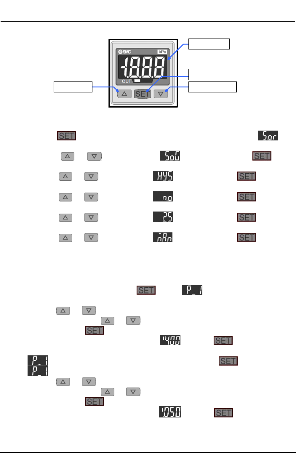
<Setting Procedure>
[U] button [V] button
[LED] panel
[SET] button
Figure 9-3-1-1 Digital Pressure Switch
1) Setting the display mode and hysteresis mode
c Keep the
button pressed for 2 sec. or longer. The display will become . (The
operation enters the display color setting mode.)
d Press the
or button to display . After that, press the button.
(When the switch is turned ON, this is displayed in green.)
e Press the
or button to display . After that, press the button. (The
operation enters the hysteresis setting mode.)
f Press the
or button to display . After that, press the button. (The
normally open operation is set.)
g Press the
or button to display . After that, press the button. (The
response time is set at 2.5 ms or less.)
h Press the
or button to display . After that, press the button. (The
manual set mode is set.)
i The numeric value is displayed in this step, and then the operation is returned to the
measurement mode.
2) Setting a detection level (threshold value and hysteresis)
c In the measurement mode, press the
button. and current threshold value are
displayed alternately.
d Press the
or button. The numeric value at the least significant digit starts flashing.
Subsequently, press the
or button to increase or decrease the numeric value.
e When pressing the
button, the flashing digit moves left.
f Perform operation steps d and e to display
. Keep the button pressed for 2
sec. or longer. (The threshold value is then set to “−60.0kPa”.)
g
and current set value are displayed alternately. Press the button.
h
and current hysteresis value are displayed alternately.
i Press the
or button. The numeric value at the least significant digit starts flashing.
Subsequently, press the
or button to increase or decrease the numeric value.
j When pressing the
button, the flashing digit moves left.
k Perform operation steps h and j to display
. Keep the button pressed for 2
sec. or longer. (The hysteresis value is then set to “0.50kPa”.)
l The operation is then returned to the measurement mode. The settings are then completed.
Rev. 1.00
FX-3R Maintenance Guide
9-6
9-4. Replacing the Vacuum Pump Parts
The reference replacement timing for the consumable parts listed below is one year after starting of
the operation. Replace or clean the consumable parts while referring to the procedure below. All
parts that need to be replaced are included in the consumable part set (part No. 40068178).
[List of Replacement Parts] (Consumable part set part No.: 40068178)
Table 9-4-1 Consumable Parts for Vacuum Pump
Inspection location Q’ty
Contents Method
Suction valve interference
prevention rubber
4
Check for deformation, wear, hardening, or
crack.
Visual check
Suction and exhaust
valves
12
Check for deformation, hardening, or
chipping.
Visual check
Exhaust valve backup 4 Check for unusual wear, hardening, or crack. Visual check
Cup packing 4 Check for unusual wear, hardening, or crack. Visual check
Gasket 4 Check for deformation, hardening, or crack. Visual check
Inside of
vacuum
pump
Suction valve backup 4 Check for unusual wear, hardening, or crack. Visual check
Nylon tube 4 Check for deformation Visual check
External
parts
Silencer 1 Check for deformation Visual check
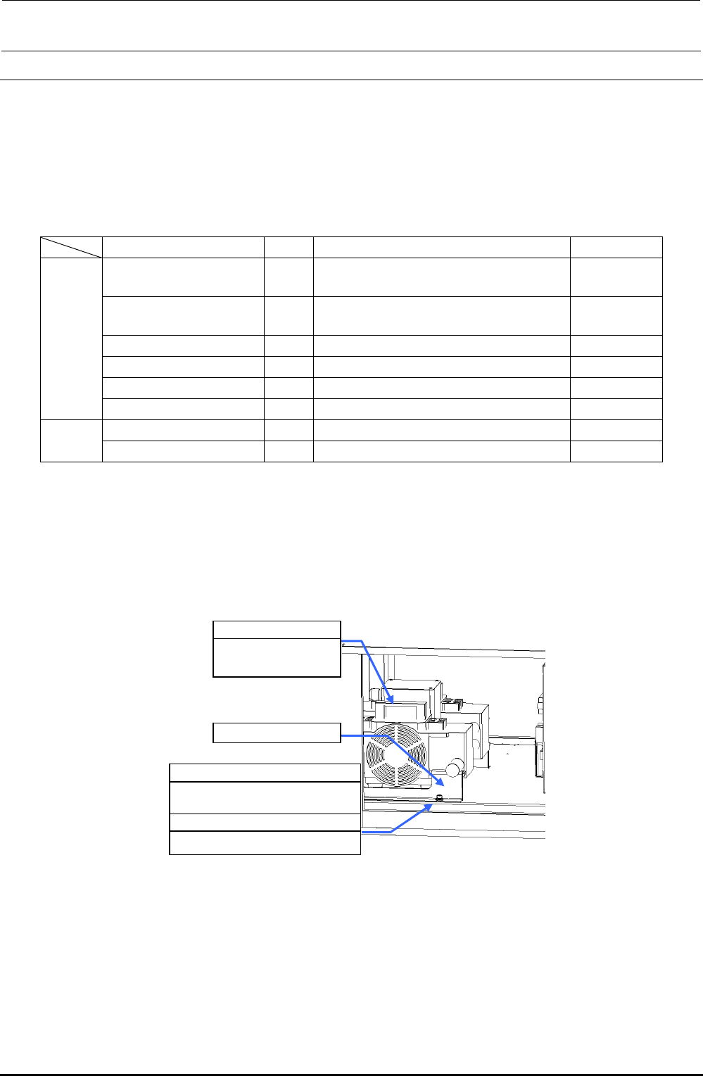
<Preparations for replacement work>
1) Make sure that the vacuum pump c is not operated.
(Great care should be taken since the vacuum pump is hot immediately after it has been
stopped.)
2) Open the cover of the electrical component unit.
SL6061292TN
SEMS cap bolt with washer
M6×12
WP0841601SC
Flat washer M8
c 40047064
Vacuum pump
assembly
d Pump support
Figure 9-4-1 Vacuum Pump
3) Disconnect the air tubes from the vacuum pump. Remove the pump support d with an Allen
wrench.
4) Pull out the vacuum pump from the main unit. (Pay special attention to the cables when pulling
out the vacuum pump.)
Rev. 1.00
FX-3R Maintenance Guide
9-7
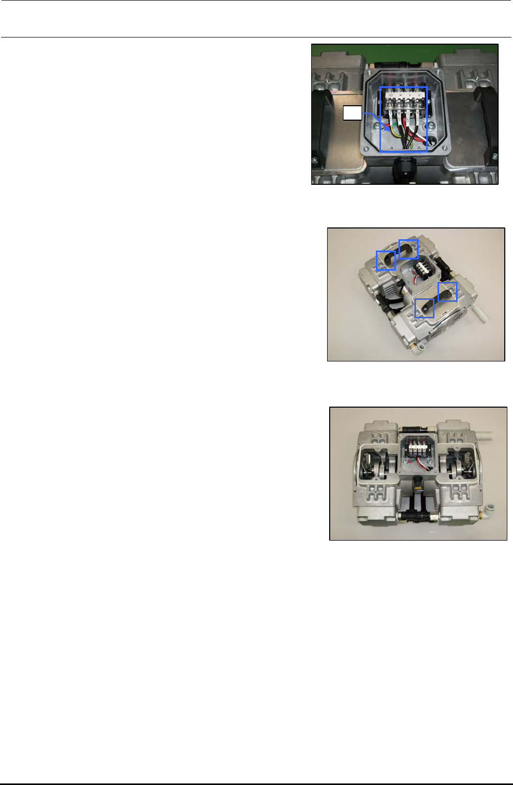
5) Open the cover of the terminal box and
disconnect the cables e from the terminal block.
e
Figure 9-4-2 Disconnecting the Cables
6) Loosen the hexagon socket head cap bolts (M6 × L16)
fixing the handle with an Allen wrench having a width
between across flats of 5 mm.
Figure 9-4-3 Removing the Bolts
7) Detach the handle and panel.
Figure 9-4-4 Detaching the
Handle and Panel
8) Place the pump vertically so that the head to be replaced is located at the top.
Rev. 1.00