GXH—1.pdf - 第207页
041 1-001 5 - B

第五章第五章
第五章第五章
第五章
电线连接图电线连接图
电线连接图电线连接图
电线连接图
本章节就各部的电线连接图进行说明。本章节就各部的电线连接图进行说明。
本章节就各部的电线连接图进行说明。本章节就各部的电线连接图进行说明。
本章节就各部的电线连接图进行说明。
因含有一定的难度,参考时请充分注意。因含有一定的难度,参考时请充分注意。
因含有一定的难度,参考时请充分注意。因含有一定的难度,参考时请充分注意。
因含有一定的难度,参考时请充分注意。
041 1-001 5-A

041 1-001 5-B
5-1
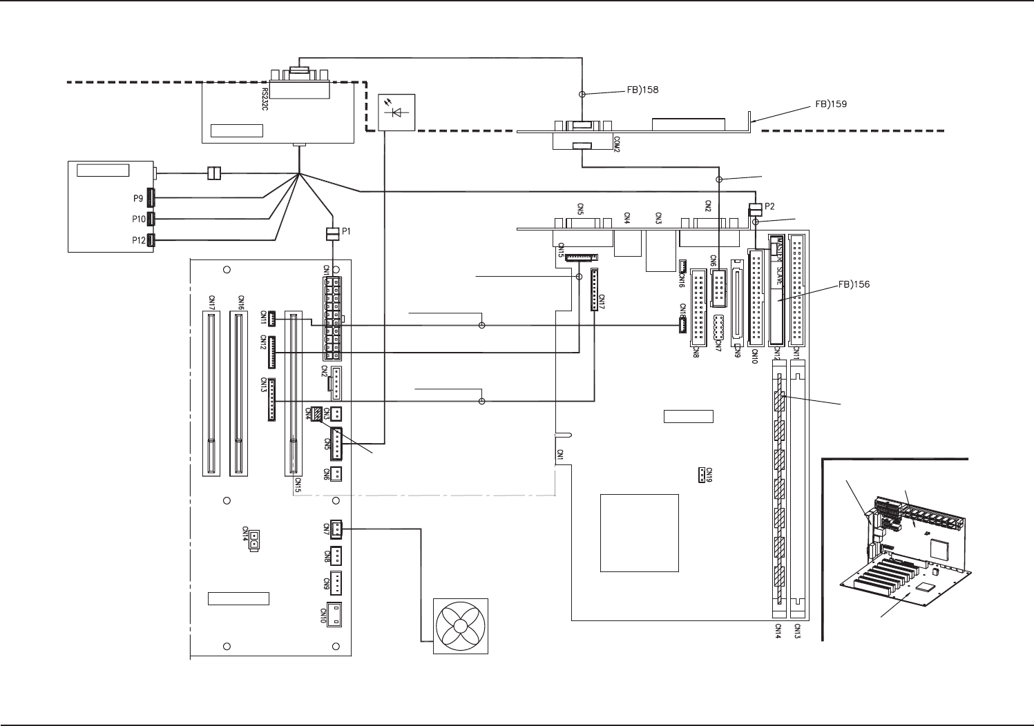
CPU2 CPU2
CPU2 CPU2
CPU2
内部连接资料内部连接资料
内部连接资料内部连接资料
内部连接资料
CPU2 CPU2
CPU2 CPU2
CPU2
内部连接资料内部连接资料
内部连接资料内部连接资料
内部连接资料
0505-002 A(M803JSB--2001)
: 630 123 0146
: 630 125 6498
: 630 126 9856
Power Unit
Battery Unit
Case LED
Back Plane
Charge and Discharge
Connector
The jumper (accessory part)
is connected to the back plane.
EXT Connector Cable
PAT-092 (provided together
with CPU board)
Provided together with FB)159
Provided together with FB)156
Memory (Provided)
CPU Board
CPU Board
COM2 Drawer Panel
Back Plane
Case Fan
RESET Board Connector Cable
PAT-311 (provided together
with CPU board)
COM2 Drawer Panel
RAS Board Connector Cable
PAT-309 (provided together
with CPU board)