00193922-01.pdf - 第113页
User Manual SIPLAC E HF Series 3 Technical data Software Vers ion SR.505.xx 05/2004 US Edition 3.7 Electrical and pneumatic connection points 113 3.7.2 P neumatic connection point Fig. 3.7 - 2 Pneumatic connection point …
3 Technical data User Manual SIPLACE HF Series
3.7 Electrical and pneumatic connection points Software Version SR.505.xx 05/2004 US Edition
112
3.7 Electrical and pneumatic connection points
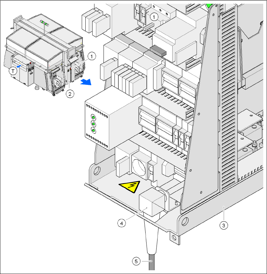
3.7.1 Electrical connection points
3
Fig. 3.7 - 1 Electrical connection points on the placement machine
3
(1) Main power switch
(2) Cover over the power supply unit
(3) Power supply unit
(4) Angle for the cable gland
(5) Power cable
(T)Direction of PCB transport
User Manual SIPLACE HF Series 3 Technical data
Software Version SR.505.xx 05/2004 US Edition 3.7 Electrical and pneumatic connection points
113
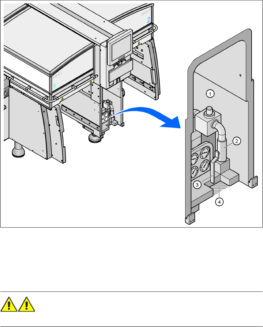
3.7.2 Pneumatic connection point
Fig. 3.7 - 2 Pneumatic connection point on the placement machine
3
(1)Pneumatic unit
(2)Coupling for connecting the compressed air hose
(3)Stop valve
(4)Recess for the air hose
WARNING
NEVER detach compressed air lines while they are still pressurized. Risk of injury. 3
3 Technical data User Manual SIPLACE HF Series
3.8 Dimensions and weight of the placement machine Software Version SR.505.xx 05/2004 US Edition
114
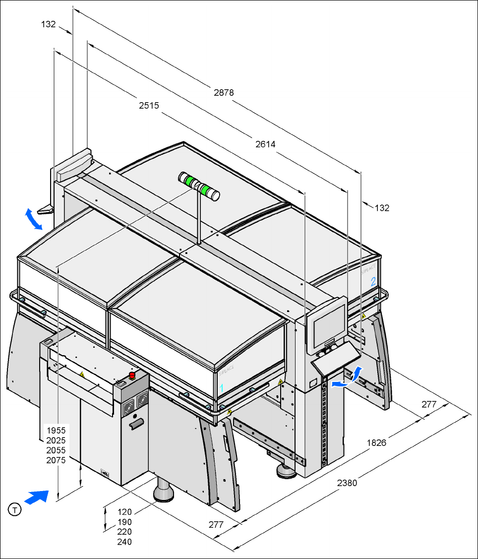
3.8 Dimensions and weight of the placement machine
3.8.1 Dimensions of the HF placement machine
3
Fig. 3.8 - 1 Dimensions of the HF placement machine (basic machine) in millimeters