00193922-01.pdf - 第252页
6 Component handling User Manual SIPLACE HF Series 6.2 Technical data f or the feeders Software Version SR.505.xx 05/2004 US Edition 252 6.2.16 Support f or waffle-p a ck trays (manual t ray) The sup port for w affle-pac…

User Manual SIPLACE HF Series 6 Component handling
Software Version SR.505.xx 05/2004 US Edition 6.2 Technical data for the feeders
251
6.2.15.1 Description of the functions
The component disposal module has essentially the same structure as a feeder. The only differ-
ence is that it has an empty tape, rather than a component tape. Faulty components can be placed
in the pockets of this empty tape without damaging them. This means that these components can
subsequently be manually checked, repaired and thus reused. The advantage of the disposal con-
veyor is that the operator can remove the separated components without having to interrupt the
placement process. Once all the pockets on the conveyor belt are full, a message appears on the
monitor, prompting the operator to remove the components. 6
6.2.15.2 System requirements
The following system requirements must be fulfilled in order to use the component disposal mod-
ule: 6
SIPLACE Pro computer software version V 2.0 or later
Station computer software version V 505.xx or later
PLEASE NOTE:
The component disposal module must be configured on the SIPLACE Pro computer and activated
on the station computer. 6
6.2.15.3 Conditions for disposal of components using the component disposal module
A component is placed on the disposal module, if the following conditions are fulfilled: 6
– The component type to be disposed of must be included in the set-up on the SIPLACE Pro
computer.
– The component must be identified for return.
– To segregate identified components that were picked up from a tray, place them back in the
tray. Only components that were wetted with flux in the dip module are placed in the component
disposal module in order to segregate them.
6 Component handling User Manual SIPLACE HF Series
6.2 Technical data for the feeders Software Version SR.505.xx 05/2004 US Edition
252
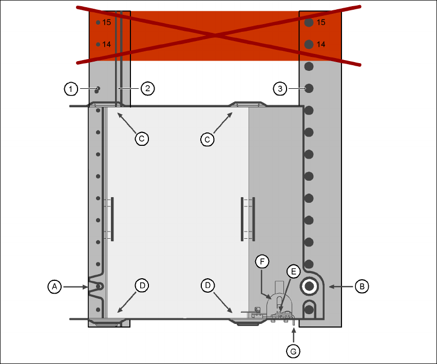
6.2.16 Support for waffle-pack trays (manual tray)
The support for waffle-pack trays allows components to be picked up from individual waffle-pack
trays. The waffle-pack trays are changed manually. 6
6
Fig. 6.2 - 16 Installation
(1) Centering pins
(2) Magnetic rail
(3) Centering ball
(14), (15) This position must not be filled.
The support for waffle-pack trays is placed on the component feeder table, just like a conveyor.
There are two different versions of the support, the only difference being the width. 6
Support for large waffle tray (260x360mm², fills 9 locations)
part no. 00116430-01 and 6
Support for small waffle tray (136x360mm², fills 5 locations)
part no. 00116432-01 6
User Manual SIPLACE HF Series 6 Component handling
Software Version SR.505.xx 05/2004 US Edition 6.2 Technical data for the feeders
253
PLEASE NOTE
– The manual tray can be set up at the following locations:
HF placement machine: locations 2 and 4
HF/3 placement machine: location 2
Feeder locations 14 and 15
must not be filled
.
– The manual tray and the nozzle changer cannot be used at the same time at location 4.
– The component trolley cannot be docked in/out while the tray is fitted.
6.2.16.1 Assembly
Æ Insert the front side of the support for waffle-pack trays into the associated centering pin (A in
Fig. 6.2 - 16
).
Æ Then position the hole on the rear side of the support for the waffle-pack tray onto the center-
ing ball on the component feeder table (B in Fig. 6.2 - 16
).
Æ Make sure the waffle-pack tray is resting securely on the component feeder table.
Æ Position one side of the waffle-pack tray carrier in the mounting (C in Fig. 6.2 - 16). Then press
the other side into the mounting (D in Fig. 6.2 - 16
).
Æ Slide the waffle-pack tray up against the stop (E in Fig. 6.2 - 16).
Æ Secure the waffle-pack tray carrier by pressing the thrust pad (F in Fig. 6.2 - 16) downwards.
Æ To remove the waffle-pack tray carrier, press the thrust pad once more.
NOTE
Using the support for small waffle-pack trays (136mm) a waffle-pack tray (JEDEC or CENELEC
waffle-pack tray) can be fitted directly to the support, in other words, without a waffle-pack tray
carrier being used. However, the thrust pad will require changing. 6
WARNING 6
All locations must be equipped with feeders in order to guarantee operational reliability.
If there are not enough feeders available, unassigned locations should be fitted with a hand
guard (dummy feeder). When a waffle-pack tray (manual tray) is set up, the remaining locations
should again be protected with a hand guard.
6.2.16.2 Changing the retainer
Æ Hold the retainer (G in Fig. 6.2 - 16) firmly. Press the thrust pad downwards (F in Fig. 6.2 - 16)
and remove the retainer by pressing it out sideways.