00193922-01.pdf - 第224页
5 Tasks on the machine User Manual SIPLACE HF Series 5.8 Refilling components Software Version SR. 505.xx 05/2004 US Edition 224 5.8 Refilling component s The onli ne help conta ins inform ation on refi lling c omponents…
User Manual SIPLACE HF Series 5 Tasks on the machine
Software Version SR.505.xx 05/2004 US Edition 5.7 Avoiding track errors
223
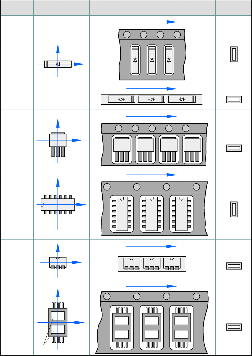
5.7.4 Component coordinate system and pick-up angle
5
Fig. 5.7 - 2 Position of the component and its pick-up angle
Special
component
Stick maga-
zine:
Chip-
components
with polarity
0402
2220
The anode must be
aligned with the +X
coordinate.
Package form
type
Coordinate system
Position in the feeder
Pick-up angle/
nozzle angle
Tape:
SOT 23
Stick maga-
zine:
Tape:
Tape:
SO-IC
DIL-IC
SOT 194
Tape:
Holes
Y
X
Y
X
Y
X
Y
X
Y
X
90°
90°
0°
90°
-90°
0°

5 Tasks on the machine User Manual SIPLACE HF Series
5.8 Refilling components Software Version SR.505.xx 05/2004 US Edition
224
5.8 Refilling components
The online help contains information on refilling components with and without barcodes.
Æ With tape feeders, make sure that you always splice on a new tape early enough so that the
feeders do not run out of components.
Æ However, do not splice the tapes too early because if you wind the tape onto the new reel after
splicing the end of the old tape, the reel with the new tape may be overfilled. The tape could
then slip off the reel and become tangled. Under certain circumstances, this could cause pick-
up errors and prolonged down times.
Æ Always insert spindles when using tape reels of 5" and larger (see Fig. 5.3 - 3) and make sure
that the dividing plates are inserted correctly (see Fig. 5.3 - 2
).
User Manual SIPLACE HF Series 5 Tasks on the machine
Software Version SR.505.xx 05/2004 US Edition 5.9 Docking the component trolley in or out
225
5.9 Docking the component trolley in or out
5.9.1 Safety instructions for docking component trolleys in and out
WARNING
To prevent accidents (risk of crushing), the component trolley may only be docked in or out by
one person.
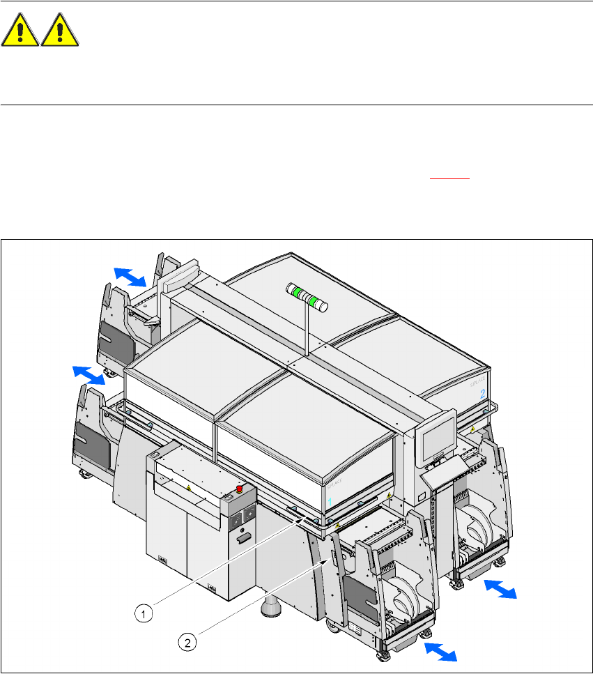
The safety concept for the component trolley change requires the operator to press two buttons
at the same time in order to dock in the component trolley. One button is beneath the protective
cover, while the other is on the hand guard side (items 1 and 2 in Fig. 5.9 - 1
). This ensures that
the operator is always standing to the side of the placement machine. The operation always re-
quires the use of both hands, thus preventing the risk of injury to the hands.
5
Fig. 5.9 - 1 Safety instructions for docking the component trolley in or out
(1) Button on top of the hand guard beneath the protective cover
(2) Button, on the side of the hand guard