00193922-01.pdf - 第135页
User Manual SIPLAC E HF Series 3 Technical data Software Vers ion SR.505.xx 05/2004 US Edition 3.11 Vision modules 135 3.1 1.2 Component vision camera (39 x 39 ) on the 6-segment Co llect&Place head 3.1 1.2.1 S truct…
3 Technical data User Manual SIPLACE HF Series
3.11 Vision modules Software Version SR.505.xx 05/2004 US Edition
134
3.11.1 Component vision camera (24 x 24) on the 12-segment Collect&Place head
3.11.1.1 Structure
3
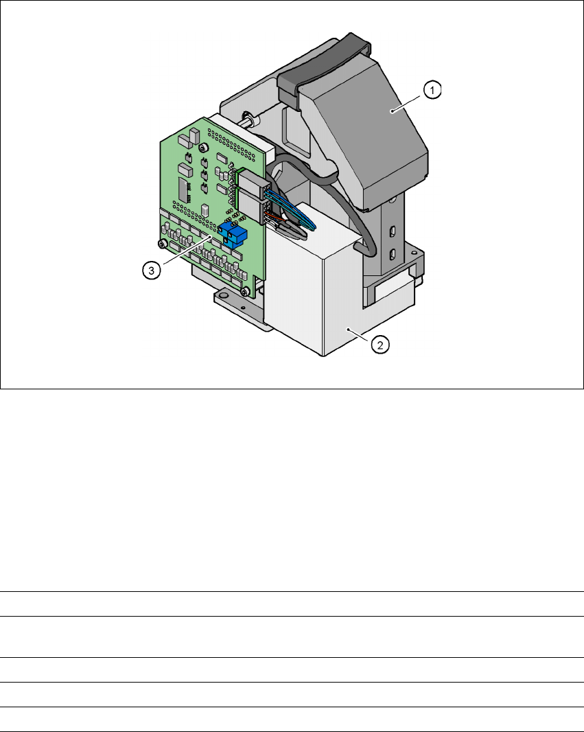
Fig. 3.11 - 2 Component vision camera (24 x 24) on the 12-segment Collect&Place head
3
(1) Component camera lens and illumination
(2) Camera amplifier
(3) Illumination control
3
3.11.1.2 Technical data
3
Component dimensions 0.6 x 0.3 mm² to 18.7 x 18.7 mm²
Range of components 0201 to PLCC44 including BGA, µBGA, flip-chip,
TSOP, QFP, PLCC, SO to SO32, DRAM
Min. lead pitch 0.5 mm
Field of vision 24 x 24 mm²
Method of illumination Front-lighting (3 levels, programable as required)
User Manual SIPLACE HF Series 3 Technical data
Software Version SR.505.xx 05/2004 US Edition 3.11 Vision modules
135
3.11.2 Component vision camera (39 x 39) on the 6-segment Collect&Place head
3.11.2.1 Structure
3
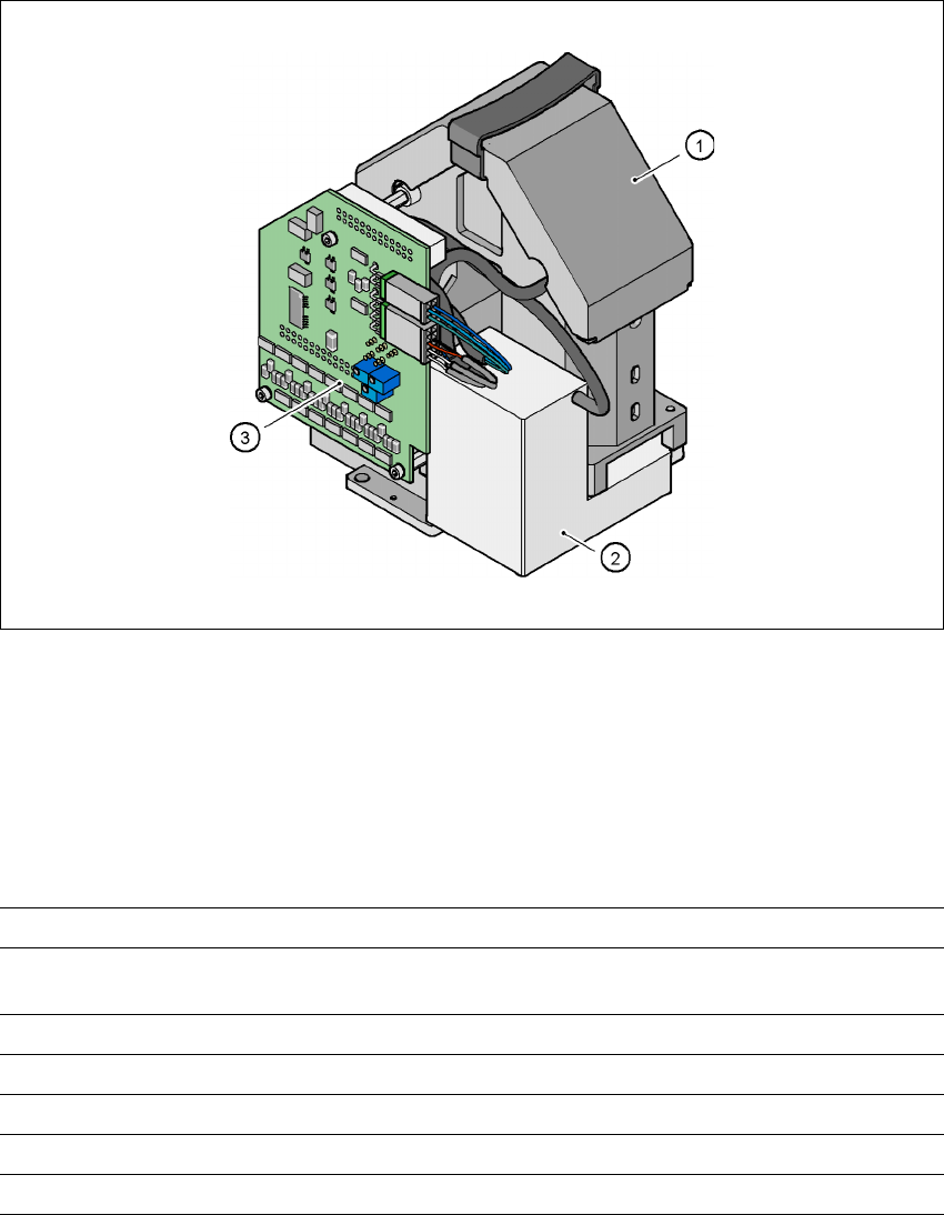
Fig. 3.11 - 3 Component vision camera (39 x 39) on the 6-segment Collect&Place head
3
(1)Component camera lens and illumination
(2)Camera amplifier
(3)Illumination control
3.11.2.2 Technical data
3
Component dimensions 1.6 x 0.8 mm² to 32 x 32 mm²
Range of components 0603 to 32x32mm²
PLCC, SO, QFP, TSDP, SOT, MELF, CHIP, IC BGA
Min. lead pitch 0.5 mm
Min. bump pitch 0.56 mm
Min. ball/bump pitch 0.32 mm
Field of vision 39 x 39 mm²
Method of illumination Front lighting (three levels, programmable as required)
3 Technical data User Manual SIPLACE HF Series
3.11 Vision modules Software Version SR.505.xx 05/2004 US Edition
136
3.11.3 Component vision camera for the TwinHead
3.11.3.1 Structure of the component vision camera (stationary, P&P (type 22) 50 x 40)
3
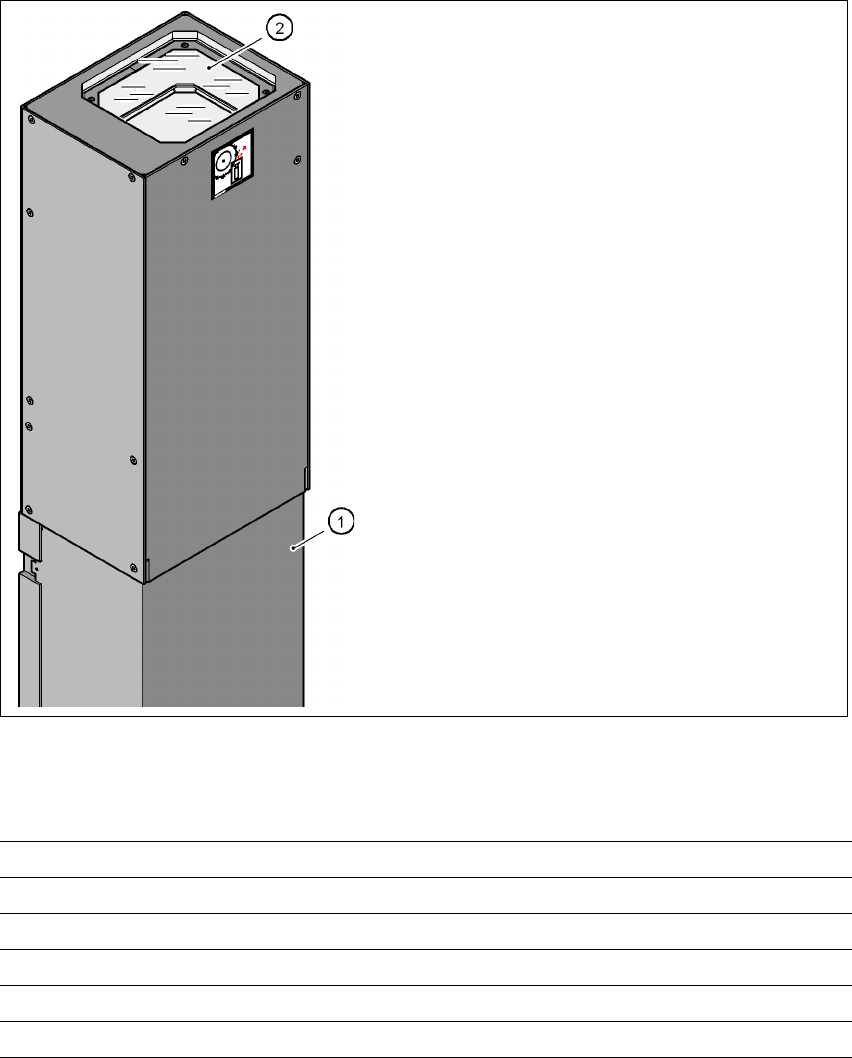
Fig. 3.11 - 4 Structure of the component vision camera (stationary, P&P (type 22) 50 x 40)
3.11.3.2 Technical data
3
(1)Camera housing with integral camera and cam-
era amplifier
(2)Glass plate - over the illumination and lens lev-
els
Component dimensions Up to 50 x 40 mm² for a single component measurement
Range of components 0603, MELF, SO, PLCC, QFP, electrolytic capacitors, BGA
Min. lead pitch 0.4 mm
Min. ball/bump diameter 0.32 mm
Field of vision 60 x 45 mm²
Method of illumination Front-lighting (6 levels, programable as required)