00193922-01.pdf - 第287页
User Manual SIPLAC E HF Series 7 Station extensions Software Vers ion SR.505.xx 05/2004 US Edition 7.1 Nozzle c hanger 287 Picking up a nozzle 7 – The Collect& Place head Z axis moves down. – The lock ing plate (item…
7 Station extensions User Manual SIPLACE HF Series
7.1 Nozzle changer Software Version SR.505.xx 05/2004 US Edition
286
7.1.2.4 Assembly
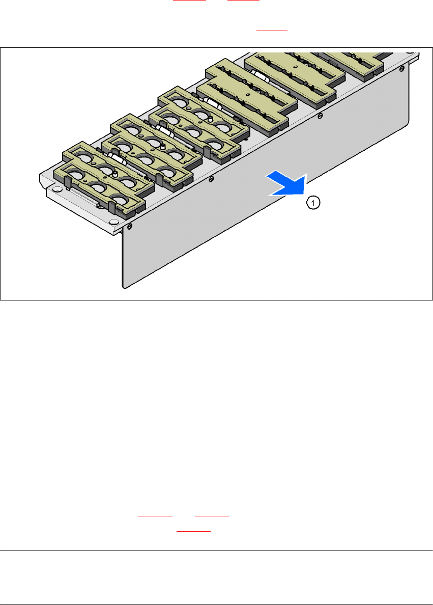
The "row 1" nozzle changer 1 (see Fig. 7.1 - 10 and 7.1 - 11) is fixed to the component trolley draw-
in device. There is an additional assembly kit for the "row 2" nozzle changer. This kit consists of
the take-off device and the nozzle reject bin (see section 7.1.2.9
).
7
Fig. 7.1 - 12 Assembly position
(1) Cover plate pointing toward the PCB conveyor
7
Æ Align the nozzle changer so that the cover plate points toward the PCB conveyor.
7.1.2.5 Description of the functions
The nozzles are seated in nozzle holders and are held in place by a movable locking plate. A
pneumatic cylinder moves the locking plate 12 mm. All the nozzles are either clamped or released,
depending on the position of the locking plate. The default position of the locking plate, i.e. if there
is no nozzle change in progress, is "closed".
Every magazine of the nozzle changer has a positioning fiducial for position detection. The mag-
azine locations are numbered consecutively from 1 - 6 for the "row 1" nozzle changers and from
7 - 12 for the "row 2" (see Fig. 7.1 - 10
and 7.1 - 11). The 6 nozzle holders in the magazines are
also numbered consecutively (see Fig. 7.1 - 13
).
PLEASE NOTE 7
Special magazines are available upon request (contact SIEMENS L&A for details) and will be
numbered differently.

User Manual SIPLACE HF Series 7 Station extensions
Software Version SR.505.xx 05/2004 US Edition 7.1 Nozzle changer
287
Picking up a nozzle 7
– The Collect&Place head Z axis moves down.
– The locking plate (item 2 in Fig. 288
, page 7.1 - 13) opens and releases the nozzles.
– The nozzle is picked up by the sleeve of the Collect&Place head.
– The Z axis moves up.
Setting down a nozzle 7
– The locking plate (item 2 in Fig. 288, page 7.1 - 13) opens and releases the nozzles.
– The Collect&Place head Z axis moves down and sets the nozzle down.
– The locking plate closes.
– The Collect&Place head Z axis moves up.
Discarding defective nozzles 7
– The Collect&Place head Z axis moves down 14 mm towards the discarding device (item 4 in
Fig. 7.1 - 10
and 7.1 - 11) and thus moves the defective nozzle into the hole in the discarding
device.
– The Z axis moves up again and the nozzle is stripped from the sleeve by spring wires.
– The nozzle drops into the reject bin.
7 Station extensions User Manual SIPLACE HF Series
7.1 Nozzle changer Software Version SR.505.xx 05/2004 US Edition
288
7
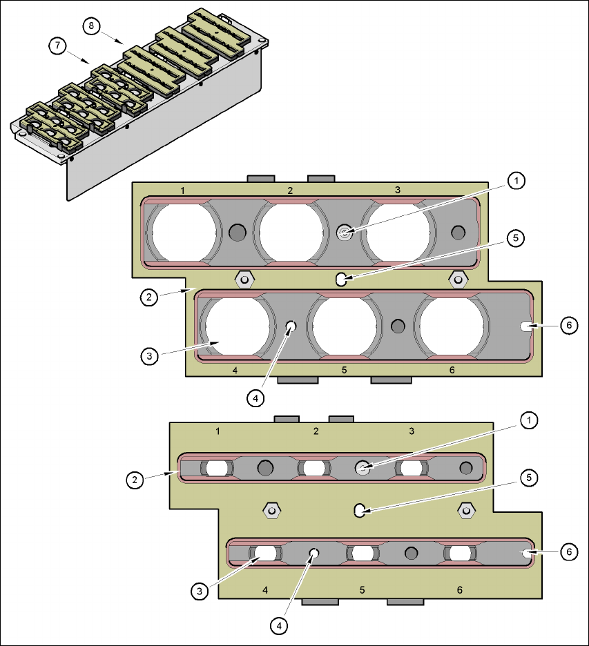
Fig. 7.1 - 13 Magazine and nozzle holders
(1) Positioning fiducial
(2) Locking plate
(3) Nozzle holder for type 9xx and 8xx nozzles
(4) Hole for the parallel pin for centering the magazines
(5) Hole for the parallel pin of the slide mechanism
(6) Slot for the parallel pin for centering the magazines
(7) Magazine for type 8xx nozzles
(8) Magazine for type 9xx nozzles