00193922-01.pdf - 第127页
User Manual SIPLAC E HF Series 3 Technical data Software Version SR.505.xx 05/2004 US Edition 3.10 Gantries 127 3.10.2 Position of the gantri es for the HF/3 placement m achine 3 Fig. 3.10 - 2 Position of the gantries f …
3 Technical data User Manual SIPLACE HF Series
3.10 Gantries Software Version SR.505.xx 05/2004 US Edition
126
3.10 Gantries
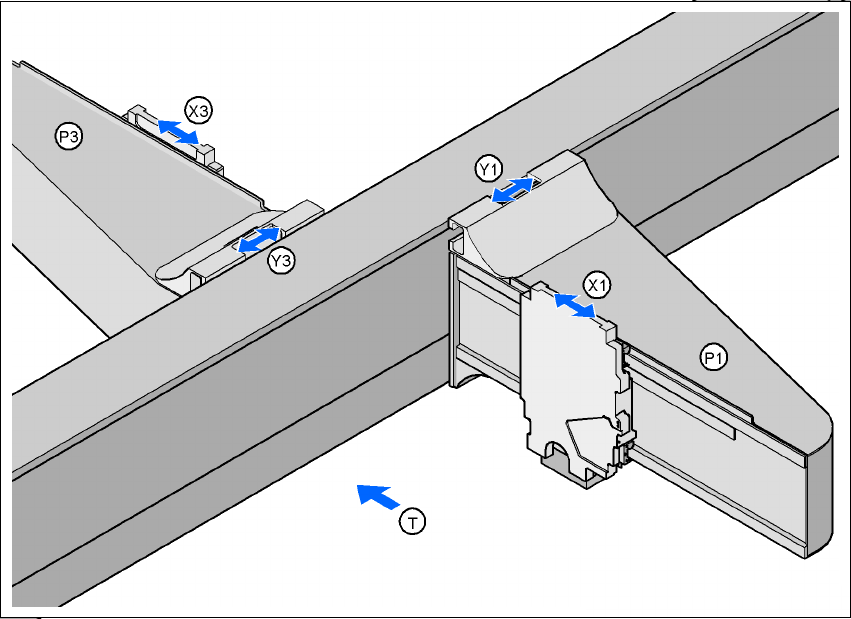
3.10.1 Position of the gantries for the HF placement machine
3
Fig. 3.10 - 1 Position of the gantries for the HF placement machine
3
P1 Gantry 1 3
X1 X axis, gantry 1 3
Y1 Y axis, gantry 1 3
P2 Gantry 2 3
X3 X axis, gantry 3 3
Y3 Y axis, gantry 3 3
(T) Direction of PCB transport 3
3
The gantry system consists of two functional groups 3
– X axis and
–Y axis
Placement area 2
Placement area 1
User Manual SIPLACE HF Series 3 Technical data
Software Version SR.505.xx 05/2004 US Edition 3.10 Gantries
127
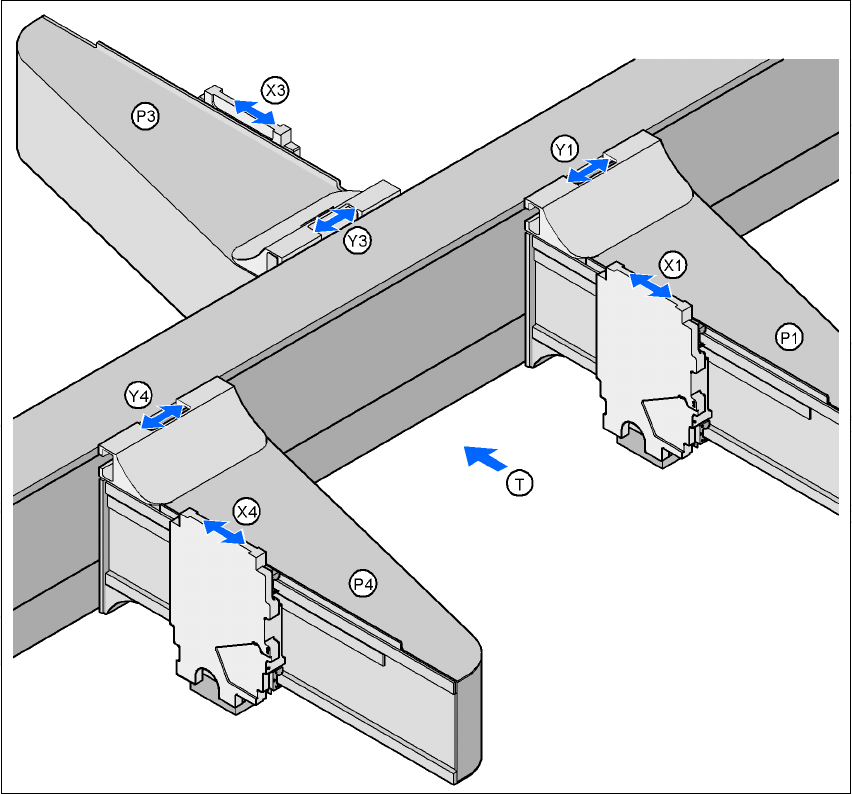
3.10.2 Position of the gantries for the HF/3 placement machine
3
Fig. 3.10 - 2 Position of the gantries for the HF/3 placement machine
3
P1 Gantry 1 3
X1 X axis, gantry 1 3
Y1 Y axis, gantry 1 3
P3 Gantry 3 3
X3 X axis, gantry 3 3
Y3 Y axis, gantry 3 3
P4 Gantry 4 3
X4 X axis, gantry 4 3
Y4 Y axis, gantry 4 3
(T) Direction of PCB transport 3
Placement area 2
Placement area 1
3 Technical data User Manual SIPLACE HF Series
3.10 Gantries Software Version SR.505.xx 05/2004 US Edition
128
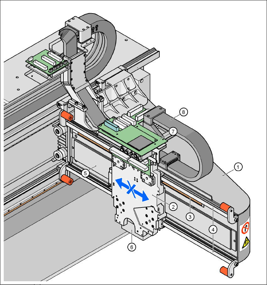
3.10.3 Structure of the X axis
3
Fig. 3.10 - 3 Structure of the X axis
3