00193922-01.pdf - 第324页
7 Station extensions User Manual SIPLACE HF Series 7.10 Component s ensor Software Version SR.505.xx 05/ 2004 US Edition 324 7.10 Compone nt sensor 7 Fig. 7.10 - 1 Placement head with component se nsor (1) Placeme nt hea…
User Manual SIPLACE HF Series 7 Station extensions
Software Version SR.505.xx 05/2004 US Edition 7.9 Feeder cover flap
323
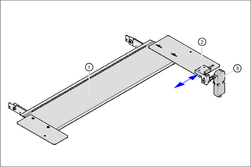
7.9 Feeder cover flap
The feeder cover flap is installed over the component feeder area. It is designed to prevent a head
crash with an upright feeder retainer that has not been engaged correctly. The feeder cover flap
can also prevent the front panel of feeders entering the placement head travelling range due to
incorrect operation.
7
Fig. 7.9 - 1 Feeder cover flap for locations 1 and 3
(1)Feeder cover flap
(2)Mechanical lock
(3)Switch in the emergency stop circuit
The feeder cover flap is available in two versions: one for location 1 or 3 and one for location 2 or 4.
The switch for the feeder cover flap is looped into the emergency stop circuit. The feeder cover
flap must be locked mechanically, which causes the switch to close the open emergency stop cir-
cuit.
7 Station extensions User Manual SIPLACE HF Series
7.10 Component sensor Software Version SR.505.xx 05/2004 US Edition
324
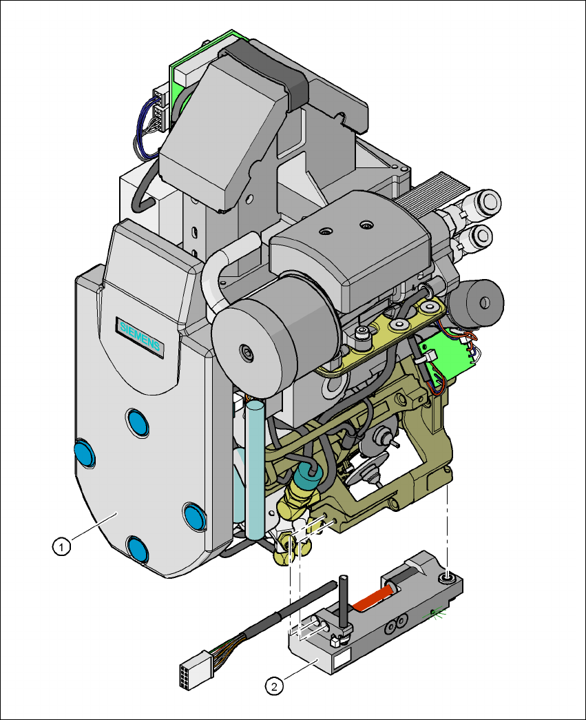
7.10 Component sensor
7
Fig. 7.10 - 1 Placement head with component sensor
(1) Placement head
(2) Component sensor
User Manual SIPLACE HF Series 7 Station extensions
Software Version SR.505.xx 05/2004 US Edition 7.10 Component sensor
325
7.10.1 Description of the functions of the component sensor
Component sensor (part no. 00118021-01)
The component sensor is fixed to the bottom of the housing of the 12-segment Collect&Place
head (see Fig. 7.10 - 1
). It scans the outline of a component and checks whether there is a com-
ponent at the nozzle. It also determines the height of the component. This data can be used to
determine whether the component is in the normal position or on edge at the nozzle. Component
heights from 0.1 to 4 mm can be checked. For larger components, only the presence of the com-
ponent at the nozzle is checked.
The component sensor is configured in the package form editor on the SIPLACE Pro computer.
Every nozzle, including the special nozzles, can be scanned by the component sensor.
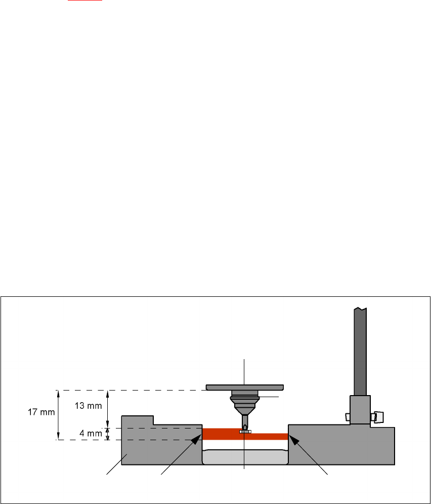
7.10.2 Measuring conditions
The two following conditions must be fulfilled in order to obtain a valid measurement:
– The light beam must touch the empty nozzle tip during the calibration process.
– The nozzle tip must be inside the light beam when it is holding a component.
– Minimum nozzle length 13 mm
– Nozzle length + component height + tolerance < 17 mm
If these conditions are fulfilled, it is possible to determine whether a component is present or ab-
sent, or to measure the component height. The minimum difference in height is 100 µm.
7
Fig. 7.10 - 2 Component sensor, working principle
7
7
Incremental disk
Component
Nozzle
IR LED PhototransistorCross-section through
component sensor