00193922-01.pdf - 第157页
User Manual SIPLAC E HF Series 4 Setting up and commissioning Software Vers ion SR.505.xx 05/2004 US Edition 4.4 Infrastructure at the inst allation location 157 Desired pr essure: 0 .46 ± 0.01 MPa, 4.6 ± 0.1 bar (d ispl…
4 Setting up and commissioning User Manual SIPLACE HF Series
4.4 Infrastructure at the installation location Software Version SR.505.xx 05/2004 US Edition
156
4.4.2 Compressed air supply
4.4.2.1 Checking the compressed air supply
Check that the compressed air supply conforms to the prescribed machine specifications (see ta-
ble in section 3.3
, page 91).
PLEASE NOTE:
The document entitled "Network configuration (electrical and compressed air) for SMD systems
on the customer's premises", part no. 00191409-xx, describes the action that can be taken to
meet the required specifications.
Æ Record the compressed air characteristics at the installation location.
4.4.2.2 Compressed air connection on the placement machine
4
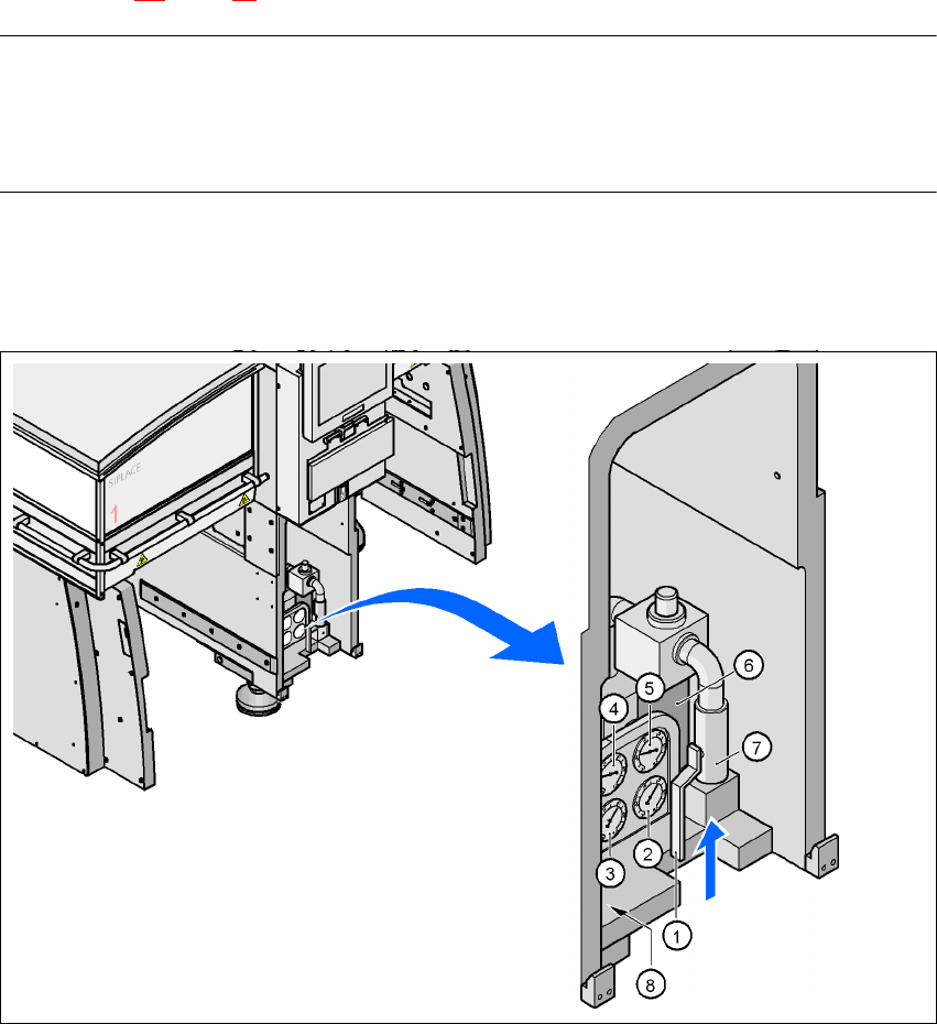
Fig. 4.4 - 1 Compressed air line connection
(1) Stop valve in the "OPEN" position
(2) Manometer for the machine component supply pressure
Desired pressure: 0.48 ± 0.025 MPa, 4.8 ± 0.25 bar (display range 0 - 0.6 MPa, 0 - 6 bar)
(3) Manometer for the gantry distributor supply pressure
User Manual SIPLACE HF Series 4 Setting up and commissioning
Software Version SR.505.xx 05/2004 US Edition 4.4 Infrastructure at the installation location
157
Desired pressure: 0.46 ± 0.01 MPa, 4.6 ± 0.1 bar (display range 0 - 0.6 MPa, 0 - 6 bar)
(4) Manometer for the bulk case feeder supply pressure
Desired pressure: 0.25 MPa ± 0.05 MPa (2.5 bar ± 0.5 bar (display range: 0 - 0.6 MPa, 0 - 6 bar)
(5) Manometer for the input pressure
Desired pressure: 0.5 - 1.0 MPa, 5 - 10 bar (display range: 0 - 1.0 MPa, 0 - 10 bar)
(6) Compressed air filter
(7) Compressed air connection
(8) Hexagon socket head screw for fixing the pneumatic board
WARNING
NEVER detach compressed air lines while they are still pressurized. Risk of injury. 4
4.4.3 Main power supply
4
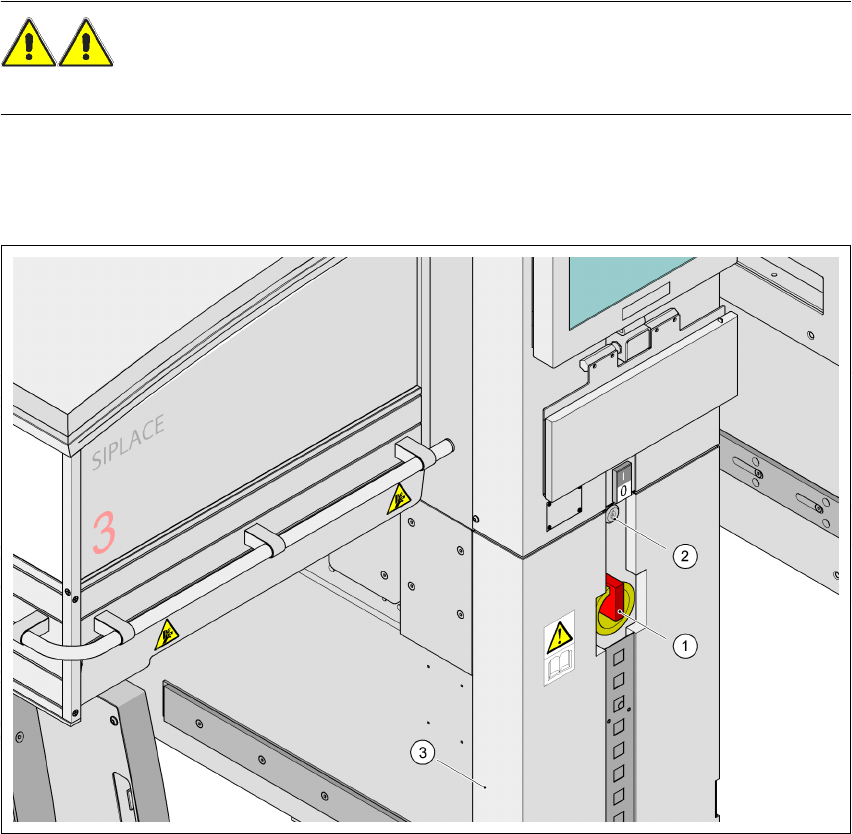
Fig. 4.4 - 2 Position of the power supply on the machine
4
(1) Main power switch
(2) Lock
(3) Cover

4 Setting up and commissioning User Manual SIPLACE HF Series
4.4 Infrastructure at the installation location Software Version SR.505.xx 05/2004 US Edition
158
4.4.3.1 Danger notes
WARNING
The placement system is supplied with 3 x 208 VAC, 3 x 230 VAC, 3 x 380 VAC, 3 x 400 VAC or
3 x 415 VAC ± 5 %, 50/60 Hz main power voltage. This means that some parts of the system
carry potentially lethal voltages - even when switched off at the main power switch. Incorrect han-
dling of the placement system can therefore result in death or severe injury or considerable dam-
age to equipment.
Æ Always follow the applicable accident prevention and DIN regulations (particularly DIN EN 60
204, part 1).
Æ Only trained and qualified personnel may remove the cover over the power supply unit and
connect the machine to the power supply.
4
4
4.4.3.2 Checking the main power supply
Check that the main power supply conforms to the prescribed machine specifications (see table
in section 3.3
, page 91).
PLEASE NOTE:
The document entitled "Network configuration (electrical and compressed air) for SMD systems
on the customer's premises", part no. 00191409-xx, describes the action that can be taken to
meet the required specifications.
4
4
4
4.4.3.3 Power supply cable - specification
The following specifications apply to the power supply cable:
5 x 6 mm² for 3 x 380 VAC / 3 x 400 VAC / 3 x 415 VAC
5 x 6 mm² for 3 x 208 VAC / 3 x 230 VAC
The color coding for the wires will depend on the country in which the system is operated.