00193922-01.pdf - 第169页
User Manual SIPLAC E HF Series 4 Setting up and commissioning Software Version SR.505.xx 05/2004 US Edition 4. 5 Setting up the placement machine 169 Æ Screw t he thread of the "HS5 0" machi ne foot into the ho…
4 Setting up and commissioning User Manual SIPLACE HF Series
4.5 Setting up the placement machine Software Version SR.505.xx 05/2004 US Edition
168
Æ Screw the thread of the "HS50" machine foot into the hole on the underside of the spacer.
Æ Align the two spacers on the underside of the machine as follows:
– The opening in the spacer on the pneumatic unit side points in the direction of PCB trans-
port (see point 4 in Fig. 4.5 - 2
on page 166).
– The opening in the spacer on the power supply side points against the direction of PCB
transport (see point 3 in Fig. 4.5 - 2
on page 166).
Æ Fix each spacer using four hexagon socket head screws M12x80 (see point 4 in Fig. 4.5 - 3)
using the size 10 mm screwdriver bit.
Setting the PCB transport height to 930 mm and 950 mm 4
You will also need the spacer for PCB transport heights of 930 mm and 950 mm.
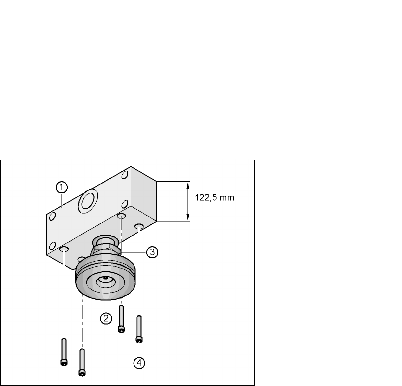
Æ Align the spacer so that the 122.5 mm side is vertical and the hole for the "HS50" machine foot
points downwards.
4
Fig. 4.5 - 4 Alignment of the spacer for transport heights of 930 and 950 mm
4
(1) Spacer height 122.5 mm
(2) "HS50" machine foot
(3) M24 lock nut
(4) Hexagon socket head screw M12x80, 4x
User Manual SIPLACE HF Series 4 Setting up and commissioning
Software Version SR.505.xx 05/2004 US Edition 4.5 Setting up the placement machine
169
Æ Screw the thread of the "HS50" machine foot into the hole on the underside of the spacer.
Æ Align the two spacers as follows:
– The opening in the spacer on the pneumatic unit side points in the direction of PCB trans-
port (see point 4 in Fig. 4.5 - 2
on page 166).
– The opening in the spacer on the power supply side points against the direction of PCB
transport (see point 3 in Fig. 4.5 - 2
on page 166).
Æ Fix each spacer using four hexagon socket head screws M12x80 (see point 4 in Fig. 4.5 - 4)
using the size 10 mm screwdriver bit.
4.5.4.2 Presetting the height of the machine feet
4
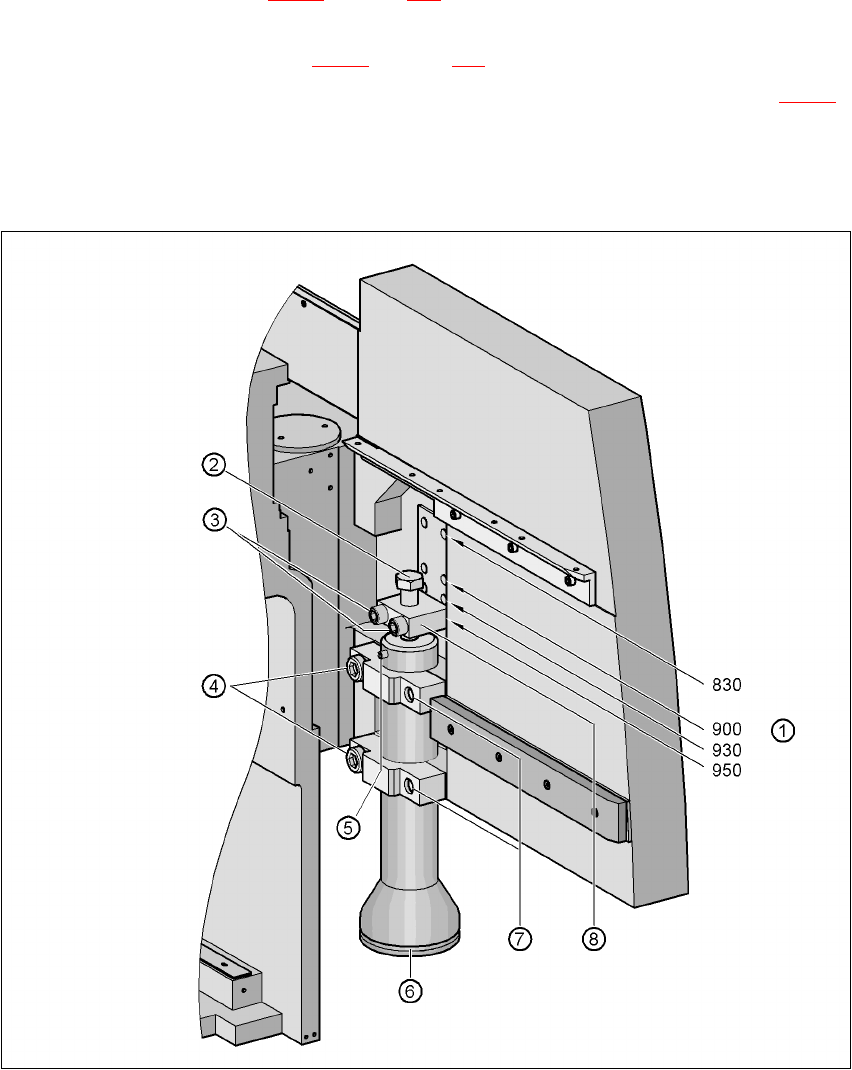
Fig. 4.5 - 5 Presetting the height of the machine feet

4 Setting up and commissioning User Manual SIPLACE HF Series
4.5 Setting up the placement machine Software Version SR.505.xx 05/2004 US Edition
170
Æ Carefully loosen the two hexagon socket head screws M24x90 (item 4 in Fig. 4.5 - 5) using the
19 mm bit, and allow the machine foot (item 6 in Fig. 4.5 - 5
) to slide down slowly until the lock-
ing pin (item 5 in Fig. 4.5 - 5
) is lying on the clamp (item 7 in Fig. 4.5 - 5).
Æ Use the 14 mm bit to loosen the two hexagon socket head screws M16x90 (item 3 in Fig. 4.5
- 5), and remove the height adjustment block (item 8 in Fig. 4.5 - 5).
Æ Use the size 36 open-ended spanner to screw the hexagon head screw M24x80 (item 2 in Fig.
4.5 - 5
) in or out of the block (item 8 in Fig. 4.5 - 5) until the same length of screw thread
emerges on both sides of the block.
Æ Fix the height adjustment block (item 8 in Fig. 4.5 - 5) at the desired height of 830 mm, 900
mm, 930 mm or 950 mm (item 1) using the two hexagon socket head screws M16x90 (item 3).
Æ Set the height for each machine foot.
Æ Now use the fork-lift to carefully lower the placement machine until the machine feet touch the
floor evenly. There should always be a second person present to ensure that the machine re-
mains stable while it is being lowered. It may be necessary to loosen the machine foot clamps
slightly.
Æ Continue lowering the machine until the machine foot touches the hexagon head screw
M24x80 (item 2) for adjusting the height.
Æ Make sure that the "HS50" machine feet (see point 2 in Fig. 4.5 - 2) do not yet touch the floor.
If necessary, screw the "HS50" machine feet into the machine or spacer slightly.