00193922-01.pdf - 第256页
6 Component handling User Manual SIPLACE HF Series 6.3 Component trolley Software Version SR. 505.xx 05/2004 US Edition 256 6.3 Com ponent tro lley Up to four compone nt troll eys may b e docke d to the S IPLACE H F plac…
User Manual SIPLACE HF Series 6 Component handling
Software Version SR.505.xx 05/2004 US Edition 6.2 Technical data for the feeders
255
6.2.17.2 Technical data
Item no. 00117010-xx 6
Assigned locations 3 6
Component size max. 36 x 36 mm²
depending on the placement head type 6
Possible coating thicknesses 25, 35, 45, 55, 65, 75 µm 6
Time required to change the coating thickness Less than 1 min. 6
Gap height tolerance ± 5 mm 6
Plate rotating speed Programmable from 0 - 10 sec.
in 0.1 sec. increments 6
Component dip time Programmable from 0 - 2 sec.
in 0.1 sec. increments 6
Flux Highly viscous flux, conductive adhesive 6
6
6 Component handling User Manual SIPLACE HF Series
6.3 Component trolley Software Version SR.505.xx 05/2004 US Edition
256
6.3 Component trolley
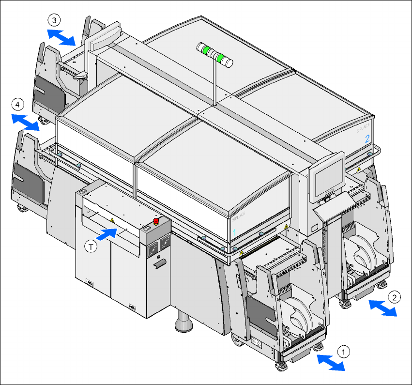
Up to four component trolleys may be docked to the SIPLACE HF placement machine. The loca-
tions are numbered as shown in the diagram below.
Fig. 6.3 - 1 Locations for the component trolleys
1, 2, 3, 4 Location no. 1, 2, 3, 4
T Direction of PCB transport
The component trolleys are stand-alone modules that can be set up at an external set-up area
with feeders. This means that the production process only has to be interrupted briefly in order to
change the component trolley.
User Manual SIPLACE HF Series 6 Component handling
Software Version SR.505.xx 05/2004 US Edition 6.3 Component trolley
257
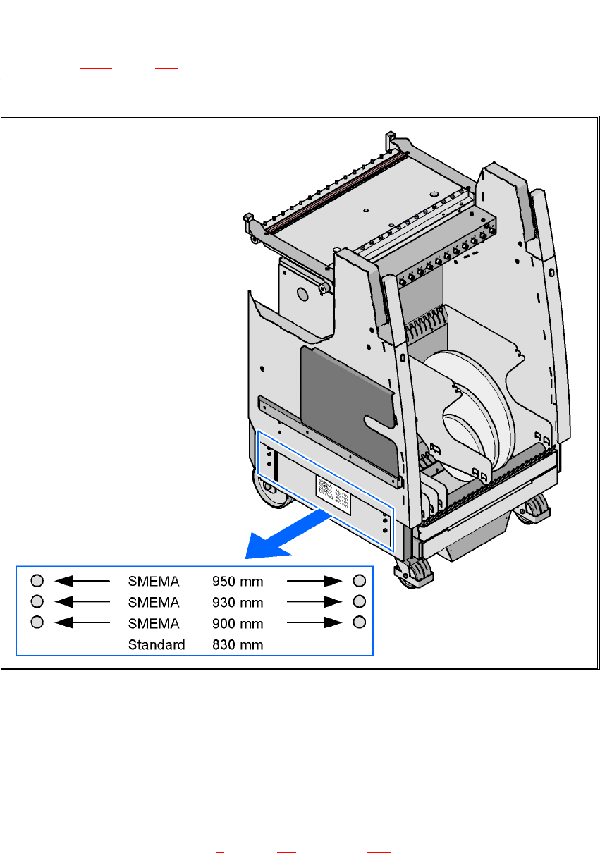
PLEASE NOTE:
At external set-up positions, you will need an external power supply for the component trolley
(see section 6.3.5, page 264).
Fig. 6.3 - 2 Component trolley with a PCB transport height of 950 mm
6
The design places considerable emphasis on ergonomics and safe operation.
– The trolleys move easily.
– No cables have to be plugged in to supply the component trolleys with power and compressed
air. The same applies to the communication interface.
– The component trolley is docked in/out the machine using a docking unit. A description of this
device can be found in chapter 5
section 5.9 from page 225 onward. It is integrated into the
safety, supply and communication circuit or is disconnected from this circuit. Electronic prox-