00193922-01.pdf - 第58页
2 Operational safety User Manual SIPLACE HF Series 2.6 Safety equipment Software Version SR.505.xx 05/2004 US Edition 58 2 Fig. 2.6 - 4 Position of switches and buttons - V iew of the PCB input side 2 (1) Em ergency s to…
User Manual SIPLACE HF Series 2 Operational safety
Software Version SR.505.xx 05/2004 US Edition 2.6 Safety equipment
57
2.6.2 Switches and buttons on the placement machine
2.6.2.1 Position of switches and buttons on the placement machine
2
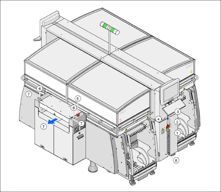
Fig. 2.6 - 3 Position of switches and buttons - View of the PCB output side
2
(1)Main power switch
(2)Stop button (black) on the operator panel on the power supply side
(3)Start button (white) on the operator panel on the power supply side
(4)Component counter on the operator panel on the power supply side
(5)Emergency stop button on the output side
(6)Start button (white) on the output side
(7)Stop button (white) on the output side
(8)Service socket in the power supply unit behind the cover
(T)PCB transport direction
2 Operational safety User Manual SIPLACE HF Series
2.6 Safety equipment Software Version SR.505.xx 05/2004 US Edition
58
2
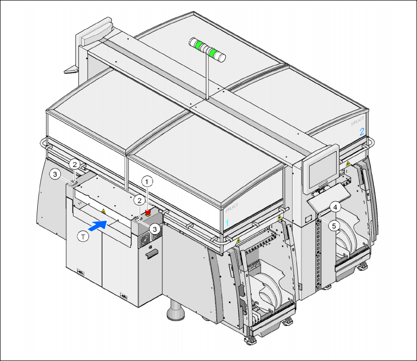
Fig. 2.6 - 4 Position of switches and buttons - View of the PCB input side
2
(1) Emergency stop button on the input side
(2) Start button (white) on the input side
(3) Stop button (white) on the input side
(4) Start button (white) on the operator panel on the compressed air unit side
(5) Stop button (black) on the operator panel on the compressed air unit side
(T)PCB transport direction

User Manual SIPLACE HF Series 2 Operational safety
Software Version SR.505.xx 05/2004 US Edition 2.6 Safety equipment
59
2.6.2.2 Position of protective switches on the placement machine
2
Fig. 2.6 - 5 Position of protective switches on the placement machine
2
(1)Protective cover switch, location 1
(2)Protective cover switch, location 2
(3)Protective cover switch, location 3
(4)Protective cover switch, location 4
(5)Protective switch for the cover on the input side of the PCB conveyor
(6)Protective switch for the cover on the output side of the PCB conveyor
(T)PCB transport direction