00193922-01.pdf - 第219页
User Manual SIPLAC E HF Series 5 Tasks on the m achine Software Vers ion SR.505.xx 05/2004 US Edition 5.4 Setting up the feeders 219 Fig. 5.4 - 2 Inserting 30 or 45 mm wide feeders on t he component feeder table (1) Feed…

5 Tasks on the machine User Manual SIPLACE HF Series
5.4 Setting up the feeders Software Version SR.505.xx 05/2004 US Edition
218
5.4.1 Preparing the component feeder table and feeder for set-up
Æ Select the location at which you wish to place the feeder.
Æ Move the placement head to the waiting position and press the emergency stop button.
Æ Open the protective cover.
Æ Clean the contact surface for the feeder and the contact surface for the feeder on the compo-
nent feeder table.
5.4.2 Inserting the feeder
Æ
First place the front of the feeder (item 1), i.e. the side with the slotted foot, onto the component
feeder table (item 4) so that the centering pin (item 2) on the component feeder table slides
into the slot in the feeder foot.
Æ Then lower the back of the feeder until the centering ball (item 3) disappears into the hole in
the feeder.
Æ Make sure that the feeders are placed correctly on the component feeder table to suit their
width (see Fig. 5.4 - 2
).
Æ Check that the feeder is firmly seated on the component feeder table.
Æ Connect the feeder plug (item 5) to the socket beneath the location.
PLEASE NOTE 5
When you connect the feeder, make sure that you use the right socket for the location since
the feeder receives the control pulse via this socket. The feeder may not work correctly if it
is not connected to the right socket. The user manual for the feeder used will contain de-
tailed information on the assignment of plugs to sockets. 5
Æ Close the protective covers.
Æ Release the emergency stop button.
Æ Switch the control on again by pressing the start button.
Æ Carry out a refill check if necessary.
Æ Continue placement.
User Manual SIPLACE HF Series 5 Tasks on the machine
Software Version SR.505.xx 05/2004 US Edition 5.4 Setting up the feeders
219
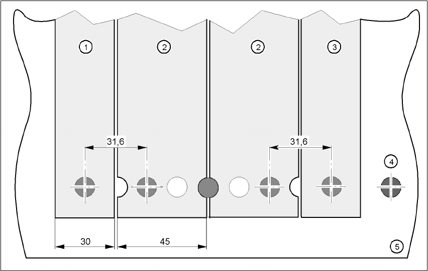
Fig. 5.4 - 2 Inserting 30 or 45 mm wide feeders on the component feeder table
(1) Feeder, 30 mm wide
(2) Feeder, 45 mm wide
(3) Feeder, 30 mm wide

5 Tasks on the machine User Manual SIPLACE HF Series
5.5 Preliminary set-up of the placement station Software Version SR.505.xx 05/2004 US Edition
220
5.5 Preliminary set-up of the placement station
Carry out the following steps to complete the preliminary set-up of the placement station.
Æ Remove the tapes from the feeders and vacuum the surfaces of the modules and the area
around the tape guide clean with the vacuum cleaner.
Æ Empty the waste tape container (see item 3 in Fig. 5.3 - 2).
Æ Clean the supporting surfaces of the feeders with a cloth moistened with alcohol.
Æ Apply a small amount of WD40 corrosion protection to the supporting surfaces with a lint-free
cloth.
Æ Use a vacuum cleaner or use a brush with short bristles
to remove loose components from the component feeder tables.
CAUTION
Avoid removing components from the magnetic rail of the component table with your fingers.
You may hurt yourself with tiny splinters of metal. 5
NOTE
The compressed air distributor rail on the component feeder tables is used to connect the
bulk case feeders. This rail runs parallel to the PCB transport and has nozzles with the
openings on the top. Make sure that the nozzles do not get dirty or come into contact with
oil or grease. Grease, oil and dirt can cause malfunctions in the feeder or may cause the
components in the feeder to become unusable! 5
Æ Check the surface of the magnetic rail for irregularities or damage and smoothen with an oil-
stone when necessary.
Æ Clean the magnetic rail with a cloth moistened with alcohol.
Æ Apply a small amount of WD40 corrosion protection to the magnetic rail with a lint-free cloth.
Æ Clean the supporting surfaces of the component feeder tables with a cloth moistened with al-
cohol, and then apply a small amount of WD40 corrosion protection with a lint-free cloth.
Æ Clean the tape container with a vacuum cleaner.
Æ Make sure that the feeders are divided up correctly.
Æ Are all the plugs of the feeder plugged in to the correct location?
Æ Make sure that the spacing in the tape transport of the feeder is correct.