00193922-01.pdf - 第336页
7 Station extensions User Manual SIPLACE HF Series 7.12 SIPLACE pr oductivity lift Software Version S R.505.xx 05/2004 US E dition 336 7.12.3 Advantages of the productivity lif t The pro ductivity lift can r aise the pr …
User Manual SIPLACE HF Series 7 Station extensions
Software Version SR.505.xx 05/2004 US Edition 7.12 SIPLACE productivity lift
335
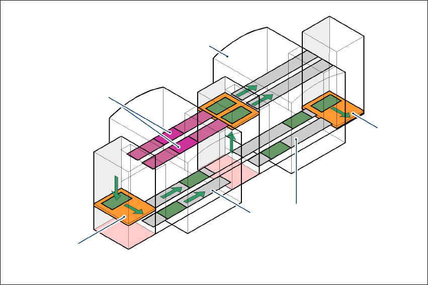
7.12.2 Implementing parallel placement
Lines with machines arranged in parallel take up a lot more space, so the parallel placement con-
cept was implemented with an underfloor conveyor and horizontal / vertical lift (HV shuttle). The
machines are still arranged in series, but the lift units and underfloor conveyors allow the line to
be operated in parallel. In this way, SIPLACE lines remain almost as compact as before.
Underfloor conveyor
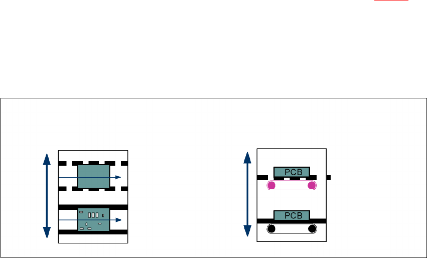
Two conveyor belts carry empty or placed PCBs underneath the machines (see Fig. 7.12 - 1).
Horizontal/vertical lift (horizontal/vertical shuttle)
There is an HV shuttle at the start of a line, between the machines and at the end of the line. It
carries the PCBs between the underfloor and processing levels, and between the two tracks on
the underfloor conveyors.
7
Fig. 7.12 - 2 Horizontal / vertical shuttle (HV shuttle), conveyor track change and lift function
Horizontal conveyor
HV shuttle
Lift function
Vertical conveyor
Unplaced
Placed
Standard
conveyor level
Underfloor
conveyor level
HV shuttle
Conveyor track change
7 Station extensions User Manual SIPLACE HF Series
7.12 SIPLACE productivity lift Software Version SR.505.xx 05/2004 US Edition
336
7.12.3 Advantages of the productivity lift
The productivity lift can raise the productivity of a line overall because it increases the placement
rates of the machines on the line.
7
Fig. 7.12 - 3 Productivity lift – avoiding stoppages
If lines are connected in parallel, individual machines may fail without bringing the entire line to a
standstill. It is also possible access individual machines while the rest of the line continues plac-
ing without interruption.
This could be for
– process-related investigations or test operation
– programming PCB fiducials, package forms or test placements
– maintenance or repairs
– operating errors, such as not splicing tapes on in good time or missing components.
Another advantage is that the line can be reconfigured as required using the software, without
having to reset the machines.
Conveyor section, processing
Placement machine
Horizontal
and vertical lift
Underfloor con-
Track change

User Manual SIPLACE HF Series 7 Station extensions
Software Version SR.505.xx 05/2004 US Edition 7.13 SIEMENS interface
337
7.13 SIEMENS interface
The conveyor interface on the placement machines from the HF series is configured to the
SMEMA standard. It is, however, still possible to use this interface in accordance with the SIE-
MENS standard. This is a significant benefit when an HF series machine is to be integrated into
older SIPLACE lines, in which case it would not be necessary to retrofit the older machines to con-
form to the SMEMA standard.
Simply configure the conveyor interface of the HF series machines to the SIEMENS standard and
connect the machines using the associated interface cable.
You can order this cable as an option with the retrofit instructions.
7.14 "Long board" option
The following PCB formats can be placed on the HF series of machines:
7
7
7
We can supply the "Long board" option as a retrofit kit for placing PCBs that are over 450 mm long.
If the "Long board" option is installed, then the following PCB formats can be processed:
7
7
7
The retrofit kit consists of the following parts:
– Complete mechanism: stopper, sensors, cables and assembly parts
– Optional CD for enabling the function on the SIPLACE Pro computer
– Retrofit instructions
Single conveyor 50 x 50 mm² to 450 x 508 mm²
Dual conveyor 50 x 50 mm² to 450 x 250 mm²
Dual conveyor in Single conveyor mode 50 x 50 mm² to 450 x 450 mm²
Single conveyor 50 x 80 mm² to 610 x 508 mm²
Dual conveyor 50 x 80 mm² to 610 x 250 mm²
Dual conveyor in Single conveyor mode 50 x 80 mm² to 610 x 450 mm²